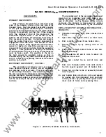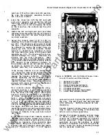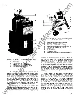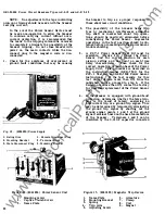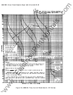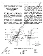
Figure 1 0. (8024842) EC-2 Overcurrent Trip
1 . Series Coil
2.
Trip Adjustment Screw
3. Opening for Time Adjustment
4.
Pickup Indicator
&
Calib. Plate
5.
Pickup Adjustment Knol;>
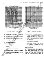
The long-time delay tripping feature can be
supplied with any one of three time-current char
acteristics which correspond to the NEMA stand
ards maximum, intermediate and minimum long
time delay operating bands . These are identified
as 1A, 1B and 1 C characteristics, respectively.
Approximate tripping time for each of these, in
the same order are 30,
1 5
and
5
seconds at 600%
of the pick-up value of current. (See time-current
characteristic curves 286B201A, B, and
C).
The tripping time may be varied within the
limits shown on the characteristic curves by turning
the time adjustment screw
(5),
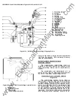
Figure 1 1. Turning
in a clockwise direction increases the tripping time;
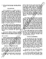
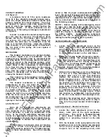
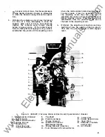
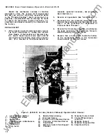
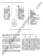
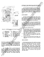
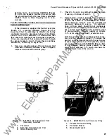
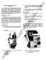
Figure 1 1. (8024843) EC-2 Overcurrent Trip With
Cover Removed.
1 . Instantaneous Calibration Spring
2. Movable Nut (Index Pointer)
3. Time-Delay Calibration Spring
4. Instantaneous Pickup Adjustment Screw
5.
Time-Delay Adjustment Screw
6. Oil Dashpot
7. Dashpot Arm
8. Connecting Link
9. Instantaneous Pickup Calibration Marks
counter-clockwise motion decreases it. The dash
pot arm (7), Figure 1 1 is indexed at four points,
maximum - 2/3 - 1/3 - minimum from the left,
as viewed in Figure 1 1. When the index mark on
the connecting link (8), Figure 1 1 , lines up with a
mark on the dashpot arm, the approximate tripping
time as shown by the charaCteristic curve is in
dicated
•
The 1A and 1B characteristic devices are
shipped with this setting at the 2/3 mark and the
lC characteristic at the 1/3 mark. The standard
characteristic curves are plotted at the same
settings.
Time values are inversely proportional to
the effective length of the dashpot arm. There
fore, the linkage setting that gives the shortest
time value is the one at which dimension "A"
Figure 1 1, is greatest.
The time adjustment
screw
(5),
Figure 1 1 , may be turned by inserting
a Phillips head screwdriver through the hole in
the front of the case, but if it is desired to relate
the linkage setting to the index marks on the
linkage it will be necessary to remove the case.
This may be done by removing the two mounting
screws, one on each side of the case, which
may be taken off without disturbing the trip unit
itself.
2 1
www
. ElectricalPartManuals
. com

