


Chapter 3
Basic Operations
23
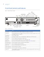
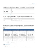
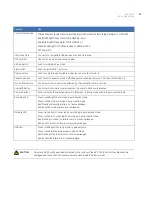
Vertical status stripe
Mimics the most severe status level of the alarm LED’s (Camera, Recording, Network, or HDD LED)
Red (flash bright). If any alarm LED is flashing red, or
Red (solid bright). If any alarm LED is solid red, or
Green (solid bright). If all status is okay on all alarm LED’s.
Off. Power off.
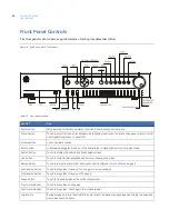
USB connectors
Connects to compatible USB devices such as a flashdrive.
DVD recorder
Use to archive video. See caution below.
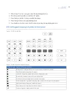
Archive button
Push to initiate
Archive mode.
Eject button
Push to eject DVD-R from drive.
Display button
Push to cycle through available multiscreen options for monitor A.
Sequence button
Push to start
Sequence mode.
Default sequence is analog cameras 1-16, then IP cameras 1-4.
Monitor A/B buttons
Controls which monitor will be affected by the analog/IP camera controls.
Analog/IP button
Controls which camera is selected when the camera buttons are pressed.
Camera buttons
Push to display the selected camera in fullscreen. In
Setup mode
used to input numerical data.
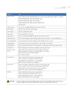
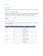
Recording LED
Green (solid bright): Recording properly, awake mode.
Green (solid dim): Recording properly, stealth mode.
Red (flashing): Recording failure, not acknowledged.
Red (solid): Recording failure, acknowledged.
Network LED
Green (solid bright): Connected and working properly, awake mode.
Green (solid dim): Connected and working properly, stealth mode.
Red (flashing): Connection failure alarm, not acknowledged.
Red (solid): Connection failure alarm, acknowledged.
HDD LED
Green (solid bright): Working properly, awake mode.
Green (solid dim): Working properly, stealth mode.
Red (flashing): Disk failure alarm, not acknowledged.
Red (solid): Disk failure alarm, acknowledged.
CAUTION
Do not use DVD’s with paper labels attached to the surface of the DVD
.
The label’s surface may become
damaged and cause the DVD media to become stuck inside the DVD recorder.
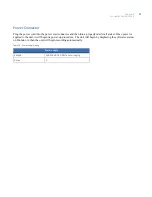
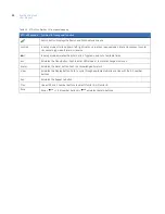
Control
Use
Содержание SymDec 16 plus 4
Страница 1: ...SymDec 16 plus 4 User Manual ...
Страница 9: ...ix Chapter 8 Maintenance support 141 Contacting technical support 142 Online publication library 142 ...
Страница 10: ...SymDec 16 plus 4 User Manual x ...
Страница 18: ...SymDec 16 plus 4 User Manual 8 ...
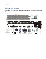
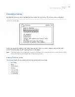
Страница 29: ...Chapter 2 Connections and Controls 19 Figure 6 Sample network diagram ...
Страница 99: ...Chapter 5 SymNav and SymBrowser 89 Figure 63 The SymNav main operation screen ...
Страница 132: ...SymDec 16 plus 4 User Manual 122 Network Figure 99 About network page Log Figure 100 About log page ...
Страница 134: ...SymDec 16 plus 4 User Manual 124 ...
Страница 144: ...SymDec 16 plus 4 User Manual 134 ...
Страница 150: ...SymDec 16 plus 4 User Manual 140 ...