1. Create a G-HUB User Account and Setup Sensor Network
If this is your first time using the iG-HUB online system site, you will need to create a new ac-
count. If you have already created an account you can skip to the “Logging into the
Online System” section. The following instructions will guide you through the account cre-
ation process.
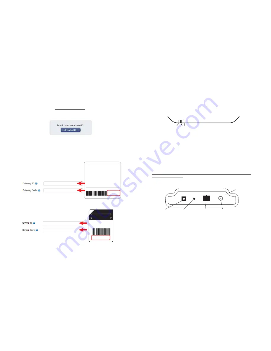
1. In a web browser, navigate to https://www.G-HUB.com.
2. Click the “Get Started Here” button to create an account.
3. Follow the on-screen instructions to enter your account and contact
information.
4. After entering your account and contact information, you will be prompted to
create your first sensor network. Simply enter a name for this network.
5. Add the information from your G-HUBLink
™
gateway then click the “Assign Gateway”
button.
6a. Add the information from your first G-HUB wireless sensor then click the
“Assign Sensor” button.
+
_
Back of Sensor
Peel
Contains: FCC ID: ZTL-RFSC1
IC: 9794A-RFSC1
Sensor ID: ######
Sensor Code: XXXXXX
6b. On the next screen, enter a name for the wireless sensor and use the
drop down to tell us how you are going to be using the wireless sensor.
(This allows us to suggest settings for your sensor.) When finished, click
the “Continue” button.
PAGE 2
PAGE 3
7. Confirmation Screen.
When you have finished adding the sensor, you will see a confirmation screen. At this
point you can assign notifications to the sensor (see Using The iG-HUB™ Online Wire-
less Sensor System) , assign additional sensors to your account or click “Done” to go to
your sensors overview page.
2. Using the G-HUBLink
™
Ethernet Gateway
1. Understanding the Ethernet Gateway Lights
Front of Ethernet Gateway
1 2 3
Light 1 - Indicates the Ethernet cable is plugged in. A green light indicates ready and
working, a red light indicates there is a problem.
Light 2 - Indicates the Ethernet has internet connectivity and can reach the online moni-
toring system. A green light indicates ready and working, a red light indicates there is a
problem. A flashing green light indicates network traffic to the internet.
Light 3 - Indicates sensor network activity. A green light indicates ready and working, a
red light indicates there is a problem. A flashing green light indicates radio traffic from the
sensors.
For help troubleshooting Ethernet gateway lights view:
http://www.G-HUB.com/support/hardware/gateways/ethernet/troubleshooting-a-G-
HUBlink-ethernet-gateway
2. Ethernet Gateway Controls
RP SMA Antenna Connector
Ethernet Port
Power Plug
Control Button
Back Panel
Using the Control Button:
1) A short press will trigger the gateway to immediately send all stored sensor messages
to the online system and download any pending system messages to deliver to the sen-
sors. (The default heartbeat for the Ethernet gateway is 5 minutes.)
2) Press and hold to reset the gateway to factory settings. Factory settings will be reset
to defaults, including the heartbeat setting of 5 minutes on both the gateway and in the
online system. DHCP, server addressing and port are all restored to default settings, for
example. You will need to login to the online system after resetting the gateway to recon-
figure the gateway to your desired settings.
Note: If your gateway powers up with the lights scrolling from left to right, it has entered into boot
loader mode accidentally. Make sure the button is free from obstruction and reboot the gateway by
removing the power plug, waiting for 10 seconds then reinserting the power plu
g.
Contains FCC ID: ZTL-RFSC1
and IC: 9794A-RFSC1
This device complies with Part 15 of the
FCC Rules. Operation is subject to the
following two conditions:
(1) this device may not cause harmful
interference and
(2) this device must accept any interference
received, including interference that may
cause undesired operation.
ID: ######
Code: XXXXXX


