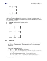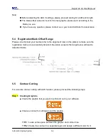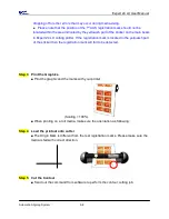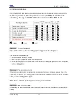
background image


Expert 24 LX user manual


Operation 

3-10 

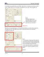
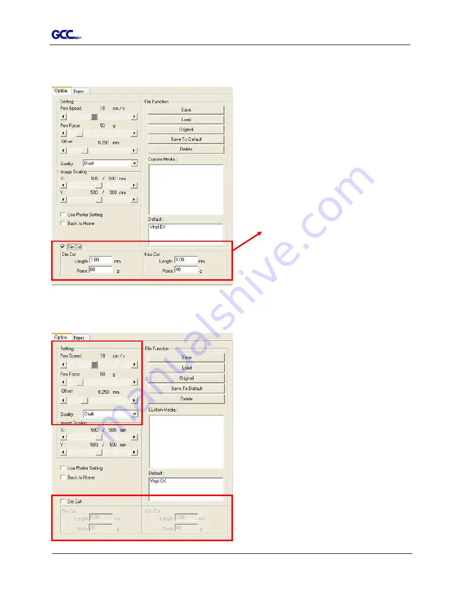
To activate the Die Cut function, go to “Option”, tick “Die Cut”, and enter the amount you wish 

for the “Length” and “Force” of both Die Cut and Kiss Cut, then click “OK” (see figure 3-9).   


When the job is completed and you untick the Die Cut function, you will be able to adjust the 

pen speed, pen force, and offset in the section on the top following normal operating 

procedures (see figure 3). 


Note:   

1. The extension of the blade has to be set to 

cut through both the top layer and the backing 

in the very beginning. You then adjust the tool 

force for the best cutting performance.   

2. Once the Die Cut function is activated, it 

will perform on all the line segments on the 

object.   


Figure 4 


*Note:   

The length setting for the 

cutting line of Die Cut is in the 

range of 0-2000mm whereas 

that of Kiss Cut is 0-100mm. 

Figure 3-9 

Содержание EXPERT 24 LX

Страница 1: ...V 10 2013 Dec EXPERT 24 LX CUTTING PLOTTER User Manual Great Computer Corporation...

Страница 2: ...fy the information contained in this user manual at any time without prior notice un authorized modification copying distribution or display is prohibited All comments queries or suggestions concernin...

Страница 3: ...peration do not touch any of the moving parts of this machine such as the carriage Also be careful to make sure that clothing and hair do not get caught Always connect the power cable to a grounded ou...

Страница 4: ...Driver Un installation 2 13 2 5 3 RS 232 Interface 2 16 2 5 4 Printer Sever Shared Setting 2 16 3 Operation 3 1 The Control Panel 3 1 3 2 VLCD 3 2 3 3 File Uploader 3 6 3 4 Data Transmission 3 7 3 5 E...

Страница 5: ...Operate 6 1 6 2 Light Indicators 6 1 6 3 Cutting Quality Problems 6 4 Appendix A 1 Expert 24 LX Specification A 1 A 2 Blade Specification A 2 A 3 CorelDRAW Plug In Instruction A 3 A 4 GreatCut Instruc...

Страница 6: ...main features of the Expert 24 LX cutting plotters Dual port connectivity USB Serial interface Up to 250 gram cutting force Up to 400 mm per second cutting speed Guaranty 3 meter 10 tracking Enhanced...

Страница 7: ...align media with clear guideline marks D Tool Carriage Performs the cutting with the installed blade or pen with AAS module E Blade Holder To hold the blade F Platen The surface for holding and suppor...

Страница 8: ...ower Connector To insert the AC power cord L Fuse 3Amp M Power Switch To turn on or off the machine N USB Connector To connect the machine and a computer through a USB cable O Serial Interface Connect...

Страница 9: ...any direction Keep enough space for the machine accessories and supplies Keep the working area stable avoiding severe vibration Keep the temperature between 15 and 30 60 86o F in the workshop Keep th...

Страница 10: ...ide vertical stand 1 Right side vertical stand 1 Support for left side 1 Support for right side 1 Stand Beam 2 Bottom Stands with wheels 2 Sliding brackets for paper take up 1 Hex Wrench M5 4 28 Socke...

Страница 11: ...screws into the holes but do not tighten them at this step Step 4 Position both the left Support and right Support perpendicularly to the T stand and put the screws into the holes and tighten them as...

Страница 12: ...tand under the plotter and insert the screws into the holes on the bottom of the plotter but do not tighten them up as shown in Figure 2 4 Step 6 Tighten the screws of step 3 and step 5 Place the slid...

Страница 13: ...1 Step 2 Install blade Figure 2 7 Push the blade to the bottom of the blade holder Figure 2 8 Step 3 Adjust the blade tip to suitable length by screwing Blade tip adjustment screw clockwise or count c...

Страница 14: ...ting quality might be affected By increasing the cutting force it might do the trick However once the blade is worn out and no longer provides a reliable cutting you should replace a new one The blade...

Страница 15: ...aten extension will help you to adjust the media precisely Figure 2 13 Step 3 Then move the pinch rollers manually to the proper position Be sure the pinch rollers must be positioned above the grid dr...

Страница 16: ...on the power the tool carriage will measure the size of the media automatically And the plotting cutter begins to work Note Always adjust the position with the pinch rollers raised Please reposition...

Страница 17: ...2 for hardware setup and Chapter 2 4 1 for media loading 2 4 3 How to change the poll size without turning off the machine Have the machine on line press origin set once and the red error light will s...

Страница 18: ...s Revision 1 1 Operation system of Windows 95 Windows NT don t support USB USB driver installation Use the USB One click Installation for quick driver installation Follow the simple steps below for dr...

Страница 19: ...before you start the driver installation 2 Choose the model you want to install from the driver list and click on Win 8 7 Vista XP Driver Manual Selection or Win 8 7 Vista XP Driver Automatic detecti...

Страница 20: ...he driver is being installed for a second time the user will be prompted as to whether a second copy of the driver installation is required 2 If the user selects yes a second copy of the driver will b...

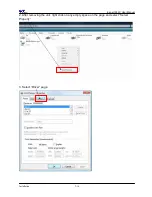
Страница 21: ...Un installation You have to remove previous version driver installed on your PC system completely before you can install the latest version successfully Please refer to below steps 1 Right click on th...

Страница 22: ...Expert 24 LX User Manual Installation 2 14 2 After removing the unit right click on any empty space on the page and select Server Property 3 Select Driver page...

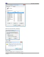
Страница 23: ...Expert 24 LX User Manual Installation 2 15 Select the model and click on Remove Click on OK Click on Yes The driver installed on PC is completely removed...

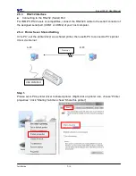
Страница 24: ...e assigned serial port COM1 or COM2 of your host computer 2 5 4 Printer Sever Shared Setting In A PC set the printer driver as a shared printer then use B PC to connect A PC s printer driver via inter...

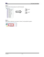
Страница 25: ...l Installation 2 17 Step 2 Click Advanced tab then choose Print directly to the printer option Step 3 Send a job to the machine to check if A PC is connected to the machine Try to send a job to check...

Страница 26: ...Expert 24 LX User Manual Installation 2 18 Step 4 Activate A PC s Printer Driver from B PC s Network Step 5 Right click on printer icon and select Connect to connect A PC s printer...

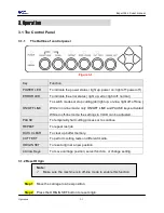
Страница 27: ...nd PAUSE keys activated While in off line mode the settings in VLCD can be adjusted PAUSE To temporarily halt cutting process or to continue REPEAT To repeat last job DATA CLEAR To clear up buffer mem...

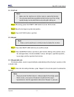
Страница 28: ...on 3 1 5 Repeat AAS Job This feature allows users to repeat AAS jobs automatically without having to operate on the computer side Step 1 When the first AAS job finishes press Repeat on the control pan...

Страница 29: ...Choose the right port connected to your computer Figure 3 2 If you are using the USB cable choose USB0 from the pull down menu If you are using a Serial cable choose either COM1 or COM2 Make sure no...

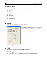
Страница 30: ...set Auto Unroll Update Setting Poll Size Click on the Poll Size button will reveal the X Y values In the case the maximum plotting length is 25000mm and the distance between the farthest two pinch rol...

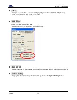
Страница 31: ...0 250 0 275 0 300 0 500 0 750 and 1 000 AAS Offset To set or modify AAS offset value You can refer to 5 3 Printer Test for more details Auto Unroll To switch options for sheet media Auto Unroll Off De...

Страница 32: ...Pause 2 after On Off line 1 and then press Origin Set 3 Step 2 Press the left key 4 and then up 5 Step 3 You have now entered the Data clear and restoring default settings mode press Data clear 6 and...

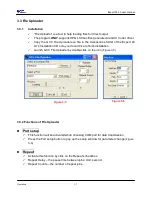
Страница 33: ...lation CD onto your local drive to finish installation Launch GCC File Uploader by double click on the icon Figure 3 5 3 3 2 Functions of File Uploader Port setup This function will be activated while...

Страница 34: ...plotter Option 1 With proper interface settings the data can be transmitted from your application software package to the cutting plotters directly Option 2 Most cutting software packages are able to...

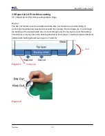
Страница 35: ...o avoid the falling of cut through materials and material jam beneath the carriage Die Cut helps you to cut through the backing of the material while Kiss Cut cuts through only the top layer but not t...

Страница 36: ...en force and offset in the section on the top following normal operating procedures see figure 3 Note 1 The extension of the blade has to be set to cut through both the top layer and the backing in th...

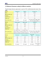
Страница 37: ...Material Vehicle stickers Reflective film Cardboard Blade red green green Blade tip length mm 0 27 0 5 0 3 Force g 85 380 165 Speed cm sec 60 3 30 Offset mm 0 275 0 5 0 5 Recommend model RX Jaguar Pu...

Страница 38: ...Wipe all the dust and dirt from the tool carriage rail Use a vacuum cleaner to clean any accumulated dirt and media residue beneath the pinch roller housing Clean the platen paper sensors and the pin...

Страница 39: ...lint free cloth or cotton swab to wipe away the accumulated dust from the rubber portion of the pinch rollers To prevent the pinch rollers from rotating while cleaning use your fingers to hold the pin...

Страница 40: ...elDraw Plug In 07_A 4 GreatCut 07_A 5 Illustrator 5 1 Introduction The Expert 24 LX cutting plotters feature a standard Automatic Aligning System AAS II to guarantee precise contour cutting quality by...

Страница 41: ...suggest white media for best cutting result It is not necessary to perform media calibration every time unless the registration marks on the printed media become undetectable in AAS sensing process 5...

Страница 42: ...have to be created on your graphic designs by cutting software like SignPal GreatCut or GCC CorelDraw plug in Hand made marks or drawings won t be reorganized by GCC cutting plotters For more details...

Страница 43: ...Layout 5 3 Printer Test Before performing AAS contour cutting it s recommended to print out a test file that you can find in the enclosed Installation CD to make sure the AAS II cutting accuracy of E...

Страница 44: ...n press Enter Test the cutting again AAS II offset X and Y value is defined as following Horizontal line is defined as X and vertical is defined as Y when facing the cutting plotter When the actual cu...

Страница 45: ...tly load your media refer to the alignment ruler on the platen to make sure the registration marks are successfully detected Deviation exceeds the range below will lead to detection failure 5 5 Contou...

Страница 46: ...ally copy the graphic and registration marks Step 2 Placing the Registration Marks The AAS Layout Instruction The Auto Detection function will succeed as long as the carriage is positioned within the...

Страница 47: ...registration mark is located in the yellowish part of the sticker then the registration mark will fail to be detected Step 3 Print the Graphics Print the graphic and the marks with your printer Scalin...

Страница 48: ...from the sides of cutter Before operating AAS change the maximum paper size in Expert 24 LX driver property STEP 1 Find the Expert 24 LX model in the Printer Fax folder of your PC STEP 2 Open the Pro...

Страница 49: ...e check the following items first Solutions If the POWER LED lights on the cutting plotter should be in a normal condition Turn off the cutting plotter and turn it on again to see if the problem still...

Страница 50: ...graph is clipped This condition indicates that the cutting graph is bigger than the cutting area You can solve the problem by 1 Reload a wider or longer media 2 Move the pinch rollers to widen the cut...

Страница 51: ...its 1 stop bit Then press ON OFF Line key to switch back to On Line mode Warning 6 Width sensor error Check that the pinch rollers are positioned above the grid drum and reload the media again 6 2 2 E...

Страница 52: ...hnical support No Error 3 Check the media drum or X motor Drum driven motor This message indicates that there might be a problem on the X axis Please check that the drums are working normally and see...

Страница 53: ...le Origin Yes Control Panel 6 LEDs 10 Keys Stand Optional Automatic Aligning System Completely Automatic Contour Cutting System for print to cut solution Temperature 15 C 30 C 60 F 86 F Operation Envi...

Страница 54: ...harp edge 265012020G The blade is 60 with Green Cap 0 50 mm blade offset For cutting thin sandblast mask and stencil with friction feed or sprocket feed machine 26500059G The blade is 60 with Blue Cap...

Страница 55: ...ing to the reference point OFFSET is the distance that the blade tip is displaced from the centerline of the blade Protrusion Length of the Blade Length of protrusion t1 t 2 2 but for your convenience...

Страница 56: ...DRAW Version 13 14 15 16 Installation 1 Check the AAS CorelDraw Installer folder in Jaguar IV Installation CD and double click the AASIIVBAInstaller exe file to run the installation program 2 Press th...

Страница 57: ...Expert 24 LX User Manual CorelDRAW Plug In A 3 User Instructions 1 Run CorelDRAW to edit your graphics and select all images at once when you wish to plot 2 Select Tools Visual Basic Play...

Страница 58: ...ess Run 3 Click on Apply and select whether you would like to add the registration marks by page size or by object Note Add Registration Mark by Object will be the default selection if you click on th...

Страница 59: ...eated automatically Note 1 The length setting will be in the range of 5 25mm according to your page size 2 Please DO NOT make any changes to the Origin section when you choose to add registration mark...

Страница 60: ...ny error occurred while media sizing For A3 size media sheet the workable area is 10mm extended from the registration mark on the left side 9mm extended from the registration mark on the right side an...

Страница 61: ...e line thickness of marks Range 1mm 2mm Optimized Setting 1mm Margin The distance between marks and images Range 0mm 50mm Optimized Setting 5mm Segmental Positioning X Step The distance of intermediat...

Страница 62: ...ate the 4 marks as shown in the picture below 4 Point Positioning Length The length of marks Range 5mm 50mm Optimized Setting 25mm Thickness The line thickness of marks Range 1mm 2mm Optimized Setting...

Страница 63: ...nd the registration marks is see the figures below Page size unit mm Suggested mark length unit mm A6 105 x 148 5 A5 148 210 8 A4 210 297 11 A3 297 420 16 A2 420 594 23 A1 594 841 and above 25 Table 1...

Страница 64: ...u are working on an extra long or large sized image to increase cutting accuracy Segmental Positioning X Step The distance of intermediate position on the X axis Y Step The distance of intermediate po...

Страница 65: ...ccuracy Multiple Copies No of X Copies The numbers of copies on X axis No of Y Copies The numbers of copies on Y axis Range 1 50 The more copies you make the more time is needed for data transmission...

Страница 66: ...ple Copies when the object to be copied is of large size with the length or width over 200mm to increase the accuracy of registration mark detection Segmental Positioning Please make sure you are happ...

Страница 67: ...ition the paper with registration marks printed by your printer on the GCC cutter Step 2 Select Files Print Please note that if you use CorelDraw X5 you must follow the steps below Click the color pag...

Страница 68: ...Expert 24 LX User Manual CorelDRAW Plug In A 3 Step 2 Go to the Layout page and select Bottom left corner at Reposition images to Step 3 Click Print You can also add a Hot Icon for the AAS II Plug in...

Страница 69: ...mands Macros Step 2 Choose GCC_CorelDraw_AASII GCCModule GCC_AASII and drag it to the commands bar Step 3 If you want to have a different icon select Tools Customization Commands Appearance to import...

Страница 70: ...elow is a step by step instruction of using the AAS function of GreatCut 2 software through CorelDRAW and Adobe Illustrator Edit your image in CorelDRAW 4 Point Positioning Step 1 Create a new file in...

Страница 71: ...Expert 24 LX User Manual GreatCut Instruction A 4 Step 2 Complete contour line settings including contour offset value and press Calculate to confirm Contour lines will be added to the images...

Страница 72: ...Expert 24 LX User Manual GreatCut Instruction A 4 Step 3 Press the Settings icon on the GreatCut 2 toolbar Step 4 Press the button on the right of Jog marks...

Страница 73: ...p Jog Marks window and click OK Step 6 Ensure the three items below are selected and click OK 4 Point Positioning Size The length of marks Range 5mm 50mm Optimized Setting 25mm Object margin The dista...

Страница 74: ...Expert 24 LX User Manual GreatCut Instruction A 4 Step 7 Click the Set Jog Marks Icon in the GreatCut 2 toolbar The system will create the 4 marks as shown in the picture below...

Страница 75: ...maller the size is the smaller the distance between the object and the registration marks is see the figures below Table 1 25mm is the suggested value for the registration mark length 2 The size of th...

Страница 76: ...Step 1 Select both the entire object including registration marks and the contour line and press the Cut icon in the GreatCut 2 toolbar Step 2 The system will activate GreatCut2 automatically and impo...

Страница 77: ...r Manual GreatCut Instruction A 4 Step 3 Select Output under File Step 4 Select Cut with AAS in Mode Tool in the Output to device window Complete the settings of AAS Offset Pressure Speed Material wid...

Страница 78: ...Expert 24 LX User Manual GreatCut Instruction A 4 Step 5 Click output and the object will be sent to GCC Cutting Plotter...

Страница 79: ...ning section to complete the contour line setting and registration mark creation procedures Adjust the size object margin and line thickness of your registration marks and the space between registrati...

Страница 80: ...Expert 24 LX User Manual GreatCut Instruction A 4 Follow the same steps in the Output section to output your image to GCC Cutting Plotter Segmental Positioning X axis Y axis...

Страница 81: ...ng section to complete the contour line setting and registration mark creation procedures Click the Set Jog Marks Icon in the GreatCut 2 toolbar and 4 marks will be created as shown in the picture bel...

Страница 82: ...ber in X Y the number of copies desired on the X Y axis and Distance in X Y distance between each copy settings then click OK Note The spacing of vertical horizontal Offset X Y should be 20mm or 0mm U...

Страница 83: ...al GreatCut Instruction A 4 The system will create several copies of the object with registration marks as shown in the picture below Follow the same steps in the Output section to output your image t...

Страница 84: ...24 LX User Manual GreatCut Instruction A 4 Edit your image in Adobe Illustrator 4 Point Positioning Step 1 Create a new file in Adobe Illustrator Step 2 Select the image and go to Contour in GreatCu2...

Страница 85: ...Cut Instruction A 4 Step 3 Complete contour line settings including contour offset value and press Calculate to confirm Contour line is now added to the object Contour offset is the distance between t...

Страница 86: ...Expert 24 LX User Manual GreatCut Instruction A 4 Step 4 Click Settings in GreatCut 2 under File Step 5 Press the button on the right of Jog marks...

Страница 87: ...rks and click OK Step 7 Ensure the three items below are selected and click OK 4 Point Positioning Size The length of marks Range 5mm 50mm Optimized Setting 25mm Object margin The distance between mar...

Страница 88: ...Expert 24 LX User Manual GreatCut Instruction A 4 Step 8 Click Set Jog Marks in GreatCut2 under File The system will create the 4 marks as shown in the picture below...

Страница 89: ...tput Step 1 Select both the entire object including registration marks and the contour line then click Cut in GreatCut2 under File Step 2 The system will activate GreatCut2 automatically and import th...

Страница 90: ...Expert 24 LX User Manual GreatCut Instruction A 4 Step 3 Select Output under File Step 4 Select Cut with AAS in Mode Tool in the Output to device window...

Страница 91: ...Expert 24 LX User Manual GreatCut Instruction A 4 Step 5 Click output and the object will be sent to GCC Cutting Plotter...

Страница 92: ...me steps in the 4 Point Positioning section to complete the contour line setting and registration mark creation procedures Adjust the size object margin and line thickness of your registration marks a...

Страница 93: ...GreatCut Instruction A 4 Click the Set Jog Marks Icon in the GreatCut 2 toolbar and 4 marks will be created as shown in the picture below Follow the same steps in the Output section to output your ima...

Страница 94: ...tion to complete the contour line setting and registration mark creation procedures Click the Set Jog Marks Icon in the GreatCut 2 toolbar and the system will create the 4 marks as shown in the pictur...

Страница 95: ...Expert 24 LX User Manual GreatCut Instruction A 4 Click Multi Copy in GreatCut2 under File...

Страница 96: ...Note The spacing of vertical horizontal Offset X Y should be 20mm or 0mm users are advised to set the Distance in X Y as 0 mm to remove the space between each copy to avoid the waste of materials The...

Страница 97: ...4 CS5 CS6 Installation 1 Check the AAS Illustrator Installer folder in Ex 24 Lx Installation CD and double click the AASIIInstaller exe file to run the installation program 2 Press the Install button...

Страница 98: ...lustrator Plug In A 5 Printer Setting Step1 Right click on the printer and select Properties to open the Printer Properties page Step2 Go to the Advanced page and make sure the Enable advanced printin...

Страница 99: ...n A 5 User Instructions 1 Open Illustrator 2 Edit your image and create a contour line Note you must have the line width set as 0 001mm 3 Click on the image and apply the AAS function File Scripts _AA...

Страница 100: ...ed 5 Three types of registration marks are introduced here 4 Point Positioning Segmental Positioning and Multiple Copies Note The values entered in the 4 Point Positioning section length thickness and...

Страница 101: ...User Manual Illustrator Plug In A 5 6 Confirm the registration marks the 4 Point Position mark is used as an illustration in the following steps 7 Click on the blank area on the page and then click Do...

Страница 102: ...Expert 24 LX User Manual Illustrator Plug In A 5 8 Hit Edit Artboards 9 Click on Presets Fit Artboard to Artwork bounds...

Страница 103: ...xpert 24 LX User Manual Illustrator Plug In A 5 10 Please move your mouse to the tool bar on the left when step 10 is finished and then click Selection Tool 11 This will take you back to the edit mode...

Страница 104: ...n A 5 12 Print out the file with the contour line and the registration marks 13 Place the printed file on the cutter lower the pinch rollers and then position the carriage at the origin of the registr...

Страница 105: ...Expert 24 LX User Manual Illustrator Plug In A 5 15 Select the cutter model position the object in the bottom left corner 16 Your job is now completed...

Страница 106: ...registration mark by page size go to Scripts under File and select _AASII_Plug_In Tick Make by page size and click Apply and the registration mark will be created on the 4 corners of the page automat...

Страница 107: ...prevent sheets dropping or any error occurred while media sizing For A3 size media sheet the workable area is 10mm extended from the registration mark on the left side 9mm extended from the registrati...

Страница 108: ...n mark by Object you will be offered three options of registration marks Firstly select the graphic which you want to add registration mark on and go to Scripts under File and select _AASII_Plug_In Ma...

Страница 109: ...he system will create the 4 marks as shown in the picture below 4 Point Positioning Length The length of marks Range 5mm 50mm Optimized Setting 25mm Thickness The line thickness of marks Range 1mm 2mm...

Страница 110: ...maller the size is the smaller the distance between the object and the registration marks is see the figures below Table 1 25mm is the suggested value for the registration mark length 2 The size of th...

Страница 111: ...are working on an extra long or large sized image to increase cutting accuracy Segmental Positioning X Step The distance of intermediate position on the X axis Y Step The distance of intermediate posi...

Страница 112: ...pies The numbers of copies on X axis No of Y Copies The numbers of copies on Y axis Range 1 50 The more copies you make the more time is needed for data transmission Numbers of X Copies Numbers of Y C...

Страница 113: ...SignPal AAS II Quick Start 3 SignPal 10 5 Feature Lists 1 Installing the SignPal 10 5 software To install the software you must have Administrator privileges To use the software you must have Adminis...

Страница 114: ...evious version of the software installed you will be prompted to overwrite the existing installation Click Yes to overwrite any previous installation of the software 8 Select the features of the softw...

Страница 115: ...for the installation a Click Disk Space b From the drop down menu select the drive you want to install to and verify that it has enough space for the installation c Click OK The installation drive cha...

Страница 116: ...nual SignPal 10 5 Instruction A 6 4 11 Once the installer is finished installing the Install Manager opens The Install Manager will automatically enable you to access the software and any optional fea...

Страница 117: ...ll to startup items to install a shortcut for the software in the Startup folder of the Start menu If this is done each time the computer starts up the software will automatically start up and minimiz...

Страница 118: ...l SignPal 10 5 Instruction A 6 6 14 Open SignPal 10 5v1 15 As you have not registered before please check on the box at bottom to register a new account 16 Input your personal information to complete...

Страница 119: ...Expert 24 LX User Manual SignPal 10 5 Instruction A 6 7 17 If you have registered before please enter your Registration code as below to open SignPal 10 5v1 software...

Страница 120: ...Expert 24 LX User Manual SignPal 10 5 Instruction A 6 8...

Страница 121: ...following Check Run in demo mode to run a demo version of any available products in any available language Ignore the password that s shown in the box use the Add button to enter any additional passw...

Страница 122: ...l 10 5 Instruction A 6 10 2 Set up your GCC Cutter on Production Manager 1 Open Production Manager 10 5v1 2 Choose and set up your GCC cutter Note that AAS II System only works on RX Jaguar IV Puma II...

Страница 123: ...Expert 24 LX User Manual SignPal 10 5 Instruction A 6 11...

Страница 124: ...Expert 24 LX User Manual SignPal 10 5 Instruction A 6 12 3 Select File Print Setup in SignPal Software 4 Select the printer and paper size...

Страница 125: ...Expert 24 LX User Manual SignPal 10 5 Instruction A 6 13 SignPal AASII Quick Start 5 Use the Rectangle Tool to create a rectangle...

Страница 126: ...Expert 24 LX User Manual SignPal 10 5 Instruction A 6 14 6 Select Effect Contour Cut Then click Apply in DesignCentral window...

Страница 127: ...ing Set the vales as 0 1cm or above and click Apply in DesignCentral window The value is to define the distance between registration marks and image area If the value is less than 0 1cm it is likely t...

Страница 128: ...6 16 Segmentation in DesignCentral window and then click Apply 10 For Multiple Copies this function is not available in SignPal Currently the Multiple Copies function is only available under CorelDraw...

Страница 129: ...cm 1m 100 in Print page 13 Load the printout vinyl on the plotter and select File Cut Contour to send data You can preview the job and change cutter s parameter settings in Properties tab of Cut Conto...

Страница 130: ...Expert 24 LX User Manual SignPal 10 5 Instruction A 6 18...

Страница 131: ...Instruction A 6 19 3 SignPal 10 5 Feature Lists Pro Master Expert Apprentice Text Text tool Arc Text Path Text Vertical Text Vertical Path Text Kerning Break apart Join Load fonts on the fly Drawing B...

Страница 132: ...Measure tool Path Editing Select Point Tool Remove point add point straighten path Round corner Sharpen Corner Optimize by Curve Optimize by smooth arc Optimize by 3point arc Make Arc Reduce Points C...

Страница 133: ...end email as jpg send email as pdf send email as native Workspaces View Design Editor Color mixer Snap Arrange Group Compound Mask Lock Guides Contour Cut Dimension Convert to outlines convert linked...

Страница 134: ...tion A 6 22 Color Trapping Smooth shadow Bitmap Marquee Move Eraser Pencil Fill Crop Autotrace Color Trace Change Color Mode Production Cut Plot Manual Split Lines Tile all copies Panel to border Auto...

Страница 135: ...6 on your MAC you may need Parallels Desktop software Window OS and Windows based Adobe Illustrator CS6 to install Windows OS in your MAC computer and run Windows based software under MAC computer Use...

Страница 136: ...th this dialog below Step 2 Create import your image file For texts 1 Enter your texts in Adobe Illustrator select the letters and click Text outline to outline the letters A contour line will be crea...

Страница 137: ...al DriectCut A 7 For Images 1 Open a new image on Illustrator and decide the size of your material 2 Select the image and click Make outline and offset to create outlines of graphics Outlines will be...

Страница 138: ...X user manual DriectCut A 7 3 Click on the image and apply the AAS function by clicking the Add registration marks command and select the registration marks needed The registration marks will be creat...

Страница 139: ...l DriectCut A 7 Step 3 Output 1 Click on Plotter Setup and select the correct model in Plotter List 2 Tick Default Environment to create Pen No 1 in the Pen section Double click Pen No 1 and complete...

Страница 140: ...Expert 24 LX user manual DriectCut A 7 3 Select the entire object and click Plotter Output 4 Output the object by clicking Export and GCC Cutting Plotter will start cutting the image...

Отзывы:

Похожие инструкции для EXPERT 24 LX