


5-18
Chapter 5 - Testing and Repair
UV Ballast Box - Cont.
Setting the Pressure Switches - Cont.
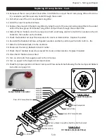
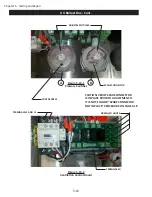
6. With gloves on and Ventilator running at 100%, turn the Adjustment Dial, as shown in Figure 5-19-1 on
Pressure Switch “A”, COUNTER CLOCKWISE until you hear a click, and the corresponding green LED lights il
-
luminate on the Ventilation Control Board, shown in Figure 5-19-2. Then turn the Adjustment Dial Pressure
Switch “B” COUNTER CLOCKWISE until you hear a “click”. The green LED lights on the Ventilation Control
Board will illuminate, and the green UVi SYSTEM ON light, on the Ventilator, will also come on. (NOTE: Both
Pressure Switches need to be on for the UV system to turn on. LED lights will always come on when the pres-
sure switch closes)
7. Once the UV Lamps are activated, all green LED lights on the Ventilation Control Board are illuminated,
and the green UVi SYSTEM ON light on the Ventilator is illuminated, gently turn Pressure Switch Adjustment
Dial on Pressure Switch “A”, CLOCKWISE until the UV Lamps deactivate, then back again slowly COUNTER
CLOCKWISE until the UV system comes back on. Repeat this process for Pressure Switch “B”. The Pressure
Switches are now set.
8. Replace the pressure switch covers.
9. Briefly secure the Ballast Box Access Cover. It must be in place to maintain proper pressurization in the
Ballast Box enclosure.
10.
Test the System:
Remove the XGS Extractor(s) at one end of the Ventilator. The UVi SYSTEM ON light(s)
must DEACTIVATE and the UV Lamps shut off shut off immediately, less than one second. If they do not,
place the XGS Extractors back in the Ventilator and repeat steps 3 through 9.
11. Repeat this process until the UVi SYSTEM ON lights remains illuminated, and the UV Lamps stay on.
12. Once the system is functioning properly, completely secure the Ballast Box Access Cover, and move on
to the next Ventilator section. Repeat as needed.
Spade Connector not in Place Procedure:
1.
Shut off Power to the UV Ventilator. Note: There are two breakers to deactivate.
a)
208/240 UV module power.
b)
120 VAC Power to the Command Center.
2.
Verify power is shut down by checking voltage on terminal 6U on the Ventilation Control
Board. Also check terminals L3/L4. Voltage for both needs to be 0. Refer to Figure 5-19-2.
3.
Place a Spade Terminal on the live Terminal shown in Figure 5-19-1, for both Pressure
Switches as needed. Return to “Setting the Pressure Switches”.
Содержание ELXC Series
Страница 40: ...4 6 INTENTIONALLY LEFT BLANK ...
Страница 74: ...7 1 Chapter 7 Wiring Diagrams ELXC GBD with AUTOSTART ...
Страница 75: ...7 2 Chapter 7 Wiring Diagrams ELXC GFBD with AUTOSTART ...
Страница 76: ...7 3 Chapter 7 Wiring Diagrams ELXC GBD UVi with AUTOSTART ...
Страница 77: ...7 4 Chapter 7 Wiring Diagrams ELXC GFBD UVi with AUTOSTART ...
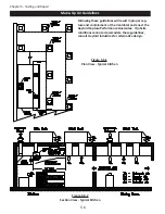
Страница 82: ...A 5 Appendix A Page A 5 Installation Requirements cont Figure A 5 1 Typical Installation MAIN FEED PIPE ...
Страница 83: ...A 6 INTENTIONALLY LEFT BLANK ...