


5-17
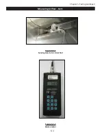
Chapter 5 - Testing and Repair
UV Ballast Box - Cont.
Pressure Switches - Cont.
have been caused by the static tap plugging with grease, to bleed off. This safety feature will automatically
shut off the UV System if the static tap becomes plugged.
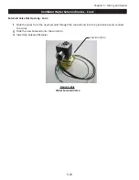
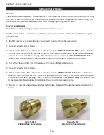
Caution: If the vinyl tube needs replacing always
use Gaylord Industries Vacuum Release Tube. Refer to the Parts on Page 6-8.
The Pressure Switches must be set prior to the initial operation of the Ventilator, and after the exhaust vol
-
ume has been verified in accordance with the Measuring Airflow section on pages 5-1 through 5-5. To set
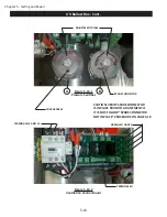
the Pressure Switches proceed as follows (Refer to Figure 5-19-1):
Caution: Testing the Pressure Switches must be performed by Gaylord Certified Service Agent. For a list
of Gaylord Certified Service Agencies (CSA’s) visit www.gaylordventilation.com and go to “Service Agen-
cies”.
Caution: The Pressure Switches are located in the Ballast Box which is only assessable from the under-
side of the Ventilator. Therefore before you get started setting the Pressure Switches be sure to provide
yourself secure means to the equipment in order to gain access to the critical components contained in
the ELXC Ballast Box.
Caution: To set the Pressure Switches the exhaust fan must be on and therefore the Ballast Box will have
live electrical components. Be extremely careful not to make contact with live electrical components. It
is recommended that gloves be worn while adjusting the switches. There is a risk of shock, injury, and /
or death from contact with live electrical components.
CAUTION: Verify that the SPADE CONNECTORS ARE IN PLACE PRIOR TO ANY ADJUSTING as illustrated in
Figure 5-19-1. If Not proceed to “Spade Connector not in Place Procedure”.
PRIOR to Starting (Site Conditions):
The Kitchen Exhaust system is to be fully balanced. All Doors and win-
dows to be closed and sealed consistent with the future operation of the kitchen. Make up air and transfer
air systems are to be activated and running during this procedure. Cooking Equipment is to be OFF. Kitch
-
en Ambient Temperatures are to be between 75ºF and 85ºF. Kitchens running outside these temperatures
may not be set correctly. A follow up must be conducted with the kitchen after it is in operation to verify
the operations of the UV system and its interlocks.
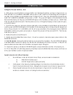
Setting the Pressure Switches
1. Confirm the Ventilators are properly balanced and verify that if so equipped the Demand Control System
is running at 100%.
2. Install all XGS Extractors.
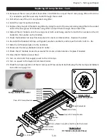
3. Remove the UV Ballast Box Access Cover located on the roof of the canopy for each Ventilator section.
A 7/16” Nut Driver will be needed. (Gently push up the inner cover, then slide over and down to remove)
4. Use a (SHORT) Philips screwdriver to remove the Cover Screws holding the Plastic Covers on both Pres
-
sure Switches, as shown in Figure 5-19-1.
5. Once the covers are removed, verify spade connectors are in place as shown in Figure 5-19-1.
CAUTION:***RISK OF SHOCK*** If the spade connectors shown are not in place turn off the power imme
-
diately. Follow the “Spade Connector not in Place Procedure” shown at the bottom of this Page.
Содержание ELXC Series
Страница 40: ...4 6 INTENTIONALLY LEFT BLANK ...
Страница 74: ...7 1 Chapter 7 Wiring Diagrams ELXC GBD with AUTOSTART ...
Страница 75: ...7 2 Chapter 7 Wiring Diagrams ELXC GFBD with AUTOSTART ...
Страница 76: ...7 3 Chapter 7 Wiring Diagrams ELXC GBD UVi with AUTOSTART ...
Страница 77: ...7 4 Chapter 7 Wiring Diagrams ELXC GFBD UVi with AUTOSTART ...
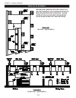
Страница 82: ...A 5 Appendix A Page A 5 Installation Requirements cont Figure A 5 1 Typical Installation MAIN FEED PIPE ...
Страница 83: ...A 6 INTENTIONALLY LEFT BLANK ...