


3-4
Chapter 3 - Maintenance
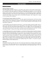
UV System Scheduled Preventive Maintenance - Cont.
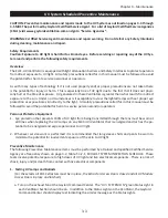
Testing UV Lamps and Ballasts - Cont.
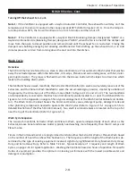
b. If the yellow
“UV
i LAMP FAILURE
” Status Light is on it indicates that one or more of the UV Lamps
are not operating. To troubleshoot and replace a lamp refer to the Troubleshooting page 4-4, and
Testing and Repair section of this manual beginning on page 5-7.
c. If the blue “
UVi SYSTEM STANDBY
” Status Light is on it indicates that one or more XGS Extractors
are not in place and/or one or more UV Module Access Doors have not been closed properly or the
internal temperature of the Ballast Box has exceeded 118° F. which activates the High Temperature
Shutdown Controller. Refer to page 4-3 for troubleshooting and corrective action for the Temperature
Shutdown Controller.
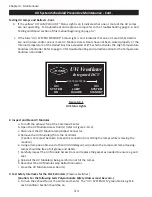
Figure 3-4-1
UV Status Lights
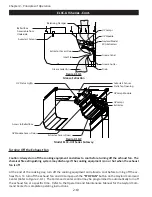
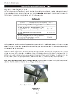
2. Inspect and Clean UV Modules
a
.
Turn off the exhaust fan at the Command Center.
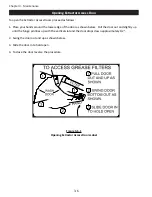
b. Open the UV Module Access Door(s) (refer to Figure 2-10-2).
c. Disconnect the UV Module Lamp Ballast Connector.
d. Remove the UV Module(s) from the Ventilator.
(Caution: Care must be taken to keep the connector from hitting the lamps while removing the
module.)
e
.
Using a damp non abrasive cloth and mild detergent, wipe down the Lamps and Lamp Housing.
Lamps should be free of all grease and debris.
f. Carefully inspect the UV Module Access Door and replace the gasket as needed to ensure a good
seal.
g. Reinstall the UV Module(s) being careful to not hit the Lamps.
h. Reconnect the UV Module Lamp Ballast Connector.
i. Close the UV Module Access Door(s).
3. Test Safety Interlocks for the XGS Extractors
(Pressure Switches)
(Caution: For the following tests Polycarbonate Safety Glasses must be worn.)
a
.
Turn on the exhaust fan at the Command Center. The “
UVi SYSTEM ON
” green Status Light in
each Ventilator Section should be on.
UVi
SYSTEM
ON
UVi
LAMP
FAILURE
UVi
SYSTEM
STANDBY
20385
SYSTEM STATUS
UVi Ventilator
Integrated DCV
Содержание ELXC Series
Страница 40: ...4 6 INTENTIONALLY LEFT BLANK ...
Страница 74: ...7 1 Chapter 7 Wiring Diagrams ELXC GBD with AUTOSTART ...
Страница 75: ...7 2 Chapter 7 Wiring Diagrams ELXC GFBD with AUTOSTART ...
Страница 76: ...7 3 Chapter 7 Wiring Diagrams ELXC GBD UVi with AUTOSTART ...
Страница 77: ...7 4 Chapter 7 Wiring Diagrams ELXC GFBD UVi with AUTOSTART ...
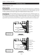
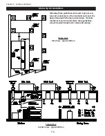
Страница 82: ...A 5 Appendix A Page A 5 Installation Requirements cont Figure A 5 1 Typical Installation MAIN FEED PIPE ...
Страница 83: ...A 6 INTENTIONALLY LEFT BLANK ...