


5-12
Chapter 5 - Testing and Repair
Replacing UV Lamp Sockets - Cont.
Instructions for Replacing UV Lamp Sockets – Wiring Harness Method
DANGER: Replacing UV Lamp Sockets as outlined on this page MUST be performed by a Gaylord Certified
Service Agent. For a list of Gaylord Certified Service Agencies (CSA’s) visit www.gaylordventilation.com
and
go to “Service Agencies” or call Gaylord Industries at 503-691-2010.
Safety Precautions
Caution: Tasks involved in replacing UV Lamp Sockets involve potential exposure to high doses of UV light
and live electrical components. There is a risk of serious injury to skin and eyes from UV light. There is a
risk of shock, injury, and /or death from contact with live electrical components.
Personal Protective Equipment
1.
Eye protection that prevents 100% of UV light being transmitted through the lens must be worn at all times
when replacing the UV Lamps on any ELX-UVi Ventilator that is energized and/or has the potential to be
energized and expose personnel to UV light.
2.
Whenever service work is performed it is recommended that long sleeve shirts and pants be worn to mini
-
mize the potential for inadvertent exposure of the skin to UVC light.
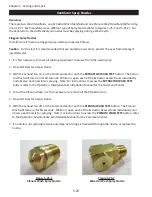
Overview
The UV Lamp Sockets Wiring Harness comes with 6 Lamp Sockets Long Wire and 6 Lamp Sockets Short Wire
connected to the base of a Pinned Receptacle.
Instructions
To replace all UV Lamp Sockets with a wiring harness carefully use the following step by step instructions.
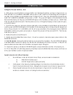
1.
Turn off all power to the Gaylord Command Center.
2.
Turn off all circuits that supply power to the UV Lamps.
3. Open the UV Module Access Door.
4.
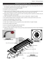
Disconnect the Lamp / Ballast Connector Cable by twisting the connector counter clockwise (refer to Fig
-
ure 5-13-1).
5.
Carefully slide out the UV Module and place on a work bench.
6.
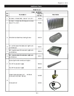
Referring to Figure 5-13-3, Remove the two bolts pc #9, washers, pc #8, Module End Cap pc #7, and the
Silicon Gasket, pc #6, from each end of the module.
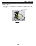
7.
Slide off each UV Light Socket, pc #5, from the Lamps at each end of the Module.
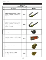
8.
Remove the four screws that hold the base of the Pinned Receptacle, pc #11, to the Lamp Module and pull
the base away from the Module until the wires are exposed.
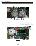
9.
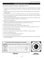
The UV Lamp Sockets are numbered 1 through 6. The wire from each UV Lamp Socket is wired back to the
Pinned Receptacle and connected to a pin labeled A through N (refer to Figure 5-13-2). There are two UV
Lamp Sockets with wire per Lamp. One is called the UV Lamp Socket Long Wire, the one that runs to the
opposite end of the Pinned Receptacle. The other is called the UV Lamp Socket Short Wire, the one that
is at the end with the Pinned Receptacle. Cut all the wires at the Pinned Receptacle. CAUTION: Do not
pull the UV Lamp Long Wire at this time. It is needed to pull the new Lamp Socket Long Wire through the
conduit tube.
Содержание ELXC Series
Страница 40: ...4 6 INTENTIONALLY LEFT BLANK ...
Страница 74: ...7 1 Chapter 7 Wiring Diagrams ELXC GBD with AUTOSTART ...
Страница 75: ...7 2 Chapter 7 Wiring Diagrams ELXC GFBD with AUTOSTART ...
Страница 76: ...7 3 Chapter 7 Wiring Diagrams ELXC GBD UVi with AUTOSTART ...
Страница 77: ...7 4 Chapter 7 Wiring Diagrams ELXC GFBD UVi with AUTOSTART ...
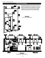
Страница 82: ...A 5 Appendix A Page A 5 Installation Requirements cont Figure A 5 1 Typical Installation MAIN FEED PIPE ...
Страница 83: ...A 6 INTENTIONALLY LEFT BLANK ...