background image

3-6

Chapter 3 - Maintenance

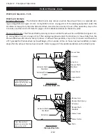
Opening Extractor Access Door

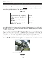
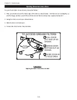
To open the Extractor Access Doors proceed as follows:

1.  Place your hands around the lower edge of the door as shown below.  Pull the door out and slightly up  

     until the hinge pin lines up with the vertical slot and the door drops down approximately 1/2”.  

2.  Swing the door out and up as shown below.

3.  Slide the door in to hold open.

4.  To close the door reverse the procedure.  

Figure 3-6-1

Opening Extractor Access Doors Label

Содержание ELXC Series

Страница 1: ...S EFFECTIVE DATE 06 2011 OPERATION MAINTENANCE INSTALLATION MANUAL For ELXC AND ELXC UV SERIES VENTILATORS Rev 07 10900 S W AVERY STREET TUALATIN OREGON 97062 U S A email info gaylordventilation com 800 547 9696 FAX 503 692 6048 www gaylordventilation com OPERATION MAINTENANCE INSTALLATION MANUAL For ELXC AND ELXC UVi SERIES VENTILATORS ...

Страница 2: ... PHOTOCOPYING RECORDING MEANS OR OTHERWISE WITHOUT PRIOR WRITTEN PERMISSION OF GAYLORD INDUSTRIES COPYRIGHT 2011 Copyright 2011 Gaylord Industries The manufacturer reserves the right to modify the materials and specifications resulting from a continuing program of product improvement or the availability of new materials ADDITIONAL COPIES 25 00 ...

Страница 3: ...quality product that exemplifies our long standing dedication to quality engineering and manufacturing Your ELXC or ELXC UVi Series Ventilator is assembled from some to the very finest components available and is designed for years of efficient effective and trouble free operation In addition the product has undergone rigorous quality control inspections and testing prior to shipment If you have a...

Страница 4: ...entative Maintenance 3 1 UV System Scheduled Preventive Maintenance 3 3 Chapter 4 Troubleshooting Trouble Shooting 4 1 Ventilator Control Matrix 4 5 Chapter 5 Testing and Repair Measuring Airflow 5 1 Makeup Air Guidelines 5 6 Replacing UV Lamps 5 7 Replacing UV Lamp Sockets 5 10 UV Ballast Box Overview 5 14 UV Ballast Box Replacing Parts 5 15 UV Ballast Box Setting Pressure Switches 5 16 Ventilato...

Страница 5: ...on so it can be accessed easily If you have any questions or concerns with the installation operation maintenance or service of your Gay lord Ventilator please contact Gaylord Industries Web www gaylordventilation com E Mail info gaylordventilation com Main Phone 503 691 2010 Toll Free 800 547 9696 Safety It is important that the operator read Chapter 2 Principle of Operation and Chapter 3 Mainten...

Страница 6: ...includes the additional feature of an Ultraviolet Light System that dramatically reduces grease accumulation in the exhaust plenum ductwork and fans Both the ELXC and ELXC UVi Ventilators come in many different models as illustrated below Your Ventilator may appear slightly different as they may have been custom designed to fit the space and application Figure 1 2 1 Model ELXC Series Wall Mounted ...

Страница 7: ... 250 F N C Thermostat standard GEBD Gaylord Electric Balancing Damper Has an electric balancing damper located at the duct collar with back draft feature GBD Gaylord Balancing Damper Mechanical balancing damper located at the duct collar with internal set GBD ES Gaylord Balancing Damper Mechanical balancing damper located at the duct collar with external set ND No Damper 3 Style Blank Wall mounted...

Страница 8: ...need to be considered with this option 7 Solid Fuel Equipment If Applicable 700 F Applications only Blank Cooking equipment powered by sources other than the burning of wood SPA Hood use XGS SPA Spark Arrestor Extractors Intended applications that utilize the burning of wood as a heat source 8 AutoStart Option Blank Indicates the hood section does not have Autostart system as required by IMC AS In...

Страница 9: ...100 Note 2 Typically ELXC Series Ventilators installed in the United States are equipped with a Gaylord Auto start Controller that automatically turns on the exhaust fan if the temperature at the sensors mounted in the canopy exceeds 90 F Refer to Figure 2 2 2 In some instances Ventilators installed outside the United States will include an Autostart Control Inclusion of an Autostart Control is de...

Страница 10: ...LXC Series Cont Figure 2 2 1 Wash Control Cabinet Figure 2 2 2 Grease Extraction Autostart Sensor Extractor Access Door Inlet Slot Grease Laden Air Balancing Damper Gaylord Model XGS Extractors Grease Canal Grease Gutter Drain Command Center ...

Страница 11: ...events cold air from coming down the duct and into the kitchen Wash Cycle Wash Cycle Overview The ELXC Series is referred to as a clean in place Ventilator as it has automatic Wash Cycles that washes away the extracted grease within the Extractors Plenum and surrounding areas with hot detergent injected wa ter The grease is flushed down into the Grease Gutter which slopes to a drain line which lea...

Страница 12: ... of fan operation stay on for 3 minutes and then shut off Refer to page 2 15 for additional details on the wash cycles Plenum Wash Cycle The Plenum Wash Cycle only comes on while the exhaust fan is off Refer to Figure 2 4 2 Using Table T 2 16 1 on page 2 16 if the cooking equipment under the Ventilator is Heavy Duty then the Plenum Wash would come on every 16 hours of exhaust fan operation stay on...

Страница 13: ...Fire Ex tinguishing System the follow will occur 1 Fire extinguishing agent will discharge through the cooking equipment nozzles the plenum nozzles and the duct nozzle s 2 The protected cooking equipment and possibly other cooking equipment will shut off Refer to the above referenced codes for specific equipment that must shut off 3 If the Fire Extinguishing System is wired to a building fire alar...

Страница 14: ...ire Extinguishing System Plenum Nozzle s Fire Extinguishing System Cooking Equipment Nozzles Illustration shows Fire Extinguishing System discharging Fire Extinguishing System Cooking Equipment Detectors Fire Extinguishing System Duct Nozzle When a Fire Extinguishing System discharges the Balancing Damper remains open or opens if it was closed If equipped with a Model GFBD Damper and the thermosta...

Страница 15: ... avoid the potential for harm to operators or service personnel Refer to Page 3 3 for complete description of safety precautions Turning On the Exhausting Fan and UV System Caution Always turn on the exhaust fan before turning on the cooking equipment Caution The chemical fire extinguishing system may discharge if the exhaust fan is not on while the cook ing equipment is on or still hot Caution Ne...

Страница 16: ... running UV Status Lights Each Ventilator section contains a bank of UV Status Lights to monitor the UV System refer to Figure 2 8 1 There are three colored lights Blue Yellow and Green They indicate the system status as follows 1 Green On The UV system is operating properly 2 Yellow On One or more UV Lamps are not operating If the yellow is on less UV is being generated however it does not preven...

Страница 17: ... in the exhaust duct Some powder may exhaust out the exhaust fan The extracted liquid grease will drain down the Extractors and into the Grease Canal which then drains down into the Grease Gutter The sticky grease will remain in the Extractors The Extractors Grease Canal and Grease Gutter are power washed periodically while the exhaust fan is on by the automatic Extractor Wash Cycle The UV Lamps a...

Страница 18: ...n To turn off the exhaust fan and UV Lamps push the STOP FAN button on the Gaylord Command Center Refer to Figure 2 9 1 The Command Center control may be programmed to automatically turn off the exhaust fan at a specific time Refer to the Operation and Maintenance Manual for the Gaylord Com mand Center for complete operating instructions UV Module Access Door Access to Ballast Box UV Status Lights...

Страница 19: ...sh the accumulated gray powder created by oxidation of the grease by the UV Lamps out of the Plenum area Refer to Figure 2 12 1 and 2 12 2 The two manifolds are independently connected to the Wash Control Cabinet typically located in or near the kitchen Refer to Figure A 5 1 in the Appendix on page A 5 for a typical arrangement of the Wash Control Cabinet and Ventila tor The Wash Control Cabinet h...

Страница 20: ...n page 2 16 if the cooking equipment under the Ventilator is Heavy Duty then the Plenum Wash would come on every 16 hours of exhaust fan operation stay on for 3 minutes and then shut off Typically the Plenum Wash Cycle will begin if the number of fan on hours has been satisfied immedi ately after the exhaust fan has been shut off Refer to page 2 15 for additional details on the Wash Cycles Figure ...

Страница 21: ...on of the Fire Extinguishing System the follow will occur 1 Fire extinguishing agent will discharge through the cooking equipment nozzles the plenum nozzles and the duct nozzle s 2 The protected cooking equipment and possibly other cooking equipment will shut off Refer to the above referenced codes for specific equipment that must shut off 3 If the Fire Extinguishing System is wired to a building ...

Страница 22: ...t Fire Protection Cont Figure 2 14 1 Fire Extinguishing System Discharge Fire Extinguishing System Duct Detector UV Module 250 F Thermostat Used only when a Gaylord Fire Balancing Damper Model GFBD is used Fire Extinguishing System Plenum Nozzle s Fire Extinguishing System Cooking Equipment Nozzles Illustration shows Fire Extinguishing System discharging Fire Extinguishing System Cooking Equipment...

Страница 23: ...termined by the type of cooking equipment involved Light Duty Light Medium Medium Duty Heavy Duty and Extra Heavy Duty as shown Table T 2 16 1 The number of hours before the Wash Cycle starts and the length of the Wash Cycle are based on aver age conditions Table T 2 16 1 shows an example of typical frequencies and length of the wash times Actual frequency and times necessary to adequately clean t...

Страница 24: ...rts Factory Set Length of Wash Cycle in min Hours of Fan Operation Before Wash Starts Factory Set Length of Wash Cycle in min Light Duty 84 3 98 3 Ovens steamers and kettles Light Medium Duty 42 3 72 3 Braising pans tilting skillets fryers open burner ranges hot top ranges and conveyor ovens Medium Duty 12 3 36 3 Griddles grooved griddles Heavy Duty 4 3 16 3 Gas and electric char broilers upright ...

Страница 25: ... EPA s Design for the Environment Program DfE which seeks to promote the use of institutional cleaners and maintenance products with improved environmental and human health characteristics FORMULA G 510EF for the Ventilator Wash System Pour FORMULA G 510EF directly into the detergent tank located inside the Wash Control Cabinet Refer to Figure 2 11 2 The detergent pump injects the detergent into t...

Страница 26: ...he use of Formula G 510EF for the life of the detergent pumping system This warranty shall not cover damages caused by any other detergent The use of any other detergent shall void this warranty All repairs and replacement parts under this warranty shall be F O B 2010 Products Inc The owner shall pay the necessary freight and delivery charges also removal and installation costs Any federal state o...

Страница 27: ...nction box located in the roof of the Ventilator Refer to figure 2 20 3 The GEBD is set up to automatically close upon shutting off the exhaust fan every night This feature prevents conditioned air from exiting the building through the Ventilator In the event of a power failure the damper will automatically open 3 Model GFBD Gaylord Fire Balancing Damper is a combination thermostatically activated...

Страница 28: ...cal Model GEBD Section View of Model GBD Other Models Look Similar The Dampers and the DSD Except Without the Motor are the same for all Models Figure 2 20 3 Table 2 20 1 Potentiometer Electric Damper Correlation Chart OPEN DSD in 100 90 80 70 60 50 40 4 1 16 3 7 8 2 15 16 2 1 8 1 1 2 15 16 3 8 ...

Страница 29: ...ould be checked This is an airtight system and fittings should be tight For com plete details on the Detergent Pump refer to the Operation and Maintenance manual for the Gaylord Com mand Center and Wash Control Cabinet 2 When a wash cycle is not on open the Extractor Access Doors and remove the Extractors Refer to Figure 3 6 1 Check the Extractors and Plenum area to ensure they are adequately clea...

Страница 30: ...indicating the date cleaned and the name of the servicing company It shall also indicate the area not cleaned It is good practice to get before and after pictures for quality control purposes CAUTION regarding pressure washing or steam cleaning If the Ventilator includes a UV System the UV Mod ules must be removed prior to pressure washing or steam cleaning Figure 3 2 2 Cleaning E L U D E H C S N ...

Страница 31: ... lighted lamps without proper eye protection or expose bare skin directly to the light All safety precautions called for in this manual must be followed to avoid the potential for harm to service personnel and or operators Personal Protective Equipment 1 Eye protection that prevents 100 of UV light from being transmitted through the lens must be worn at all times when replacing the UV Lamps on any...

Страница 32: ... off the exhaust fan at the Command Center b Open the UV Module Access Door s refer to Figure 2 10 2 c Disconnect the UV Module Lamp Ballast Connector d Remove the UV Module s from the Ventilator Caution Care must be taken to keep the connector from hitting the lamps while removing the module e Using a damp non abrasive cloth and mild detergent wipe down the Lamps and Lamp Housing Lamps should be ...

Страница 33: ...em On green Status Light in each Ventilator Section should be on b Open one UV Module Access Door refer to Figure 2 10 2 Note If there are two UV Module Access Doors always open the shortest door for the test The blue UVi System Standby Status Light should come on If this action does not occur immediately shut down the exhaust fan at the Command Center refer to the Trouble Shooting section beginni...

Страница 34: ...the lower edge of the door as shown below Pull the door out and slightly up until the hinge pin lines up with the vertical slot and the door drops down approximately 1 2 2 Swing the door out and up as shown below 3 Slide the door in to hold open 4 To close the door reverse the procedure Figure 3 6 1 Opening Extractor Access Doors Label ...

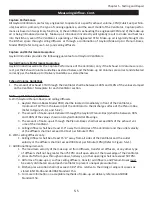
Страница 35: ...ld be adjusted to direct the air away from the Ventilator Directing or forcing the make up air at the Ventilator typically creates cross drafts resulting in smoke loss Refer to page 5 5 for guidance E Inadequate make up air 1 Make up air must be supplied for replacement of air exhausted through all kitchen exhaust systems Refer to page 5 5 for guidance 2 A general rule of thumb is that 60 of the r...

Страница 36: ... instructions on corrective action B Fan drive belt is slipping 1 Tighten belt and then measure exhaust volume to verify Refer to instructions on measuring exhaust volume beginning on page 5 1 C Fan is running in reverse 1 Contact electrical contractor to wire correctly 1 The Wash Cycle is not adequately cleaning the Extractors or Plenum A The water supply is turned off or partially off 1 Check th...

Страница 37: ...tions on replacing 2 Check the removable filter in front of the Ballast Box Ventilation Fan to see that it is not clogged or that air inlet to the fan or the louvers at the air outlet is not blocked by building insulation or any other material Clean the filter or replace with a new filter and or remove the material that is blocking the air inlet or outlet 3 Building insulation has been placed over...

Страница 38: ...ecure any loose connections between the Ventilator an the Command Center 5 A UV Ballast Box located on the top of the Ventilator is too hot 1 Refer to line 1 F on the previous page for corrective action 2 Check out removable filter Shake out and replace B Cooling fan opening and vents are covered up with insulation 1 Remove all obstructions from the inlet to the fan and the exit vents Access to th...

Страница 39: ...ire Balancing Damper will close after the 15 minute cool down time The Dampers are always open when the exhaust fan is on The Front Wash may be on when the fan is on The Front Wash comes on after a timed number of hours the exhaust fan is on The Front wash only comes on when the exhaust fan is on It will not come on when the exhaust fan is off Refer to the Typical Example of Frequency and Length o...

Страница 40: ...4 6 INTENTIONALLY LEFT BLANK ...

Страница 41: ...the exhaust fan is operating properly The exhaust volume for each Ventilator section is stamped on the Ventilator Nameplate refer to Figure 5 4 1 on page 5 4 Measuring Airflow The Ventilator exhaust volume is determined by measuring the air inlet velocity and using FPM to CFM Table T 5 4 1 to convert the recorded velocity FPM to an exhaust volume in CFM Per Lineal Ft of Ventila tor This method req...

Страница 42: ...FM is not within acceptable range then corrective action must be taken to bring the exhaust volume within design 18 If the Ventilator does not include a Balancing Damper the exhaust volume must be increased or de creased by adjusting the exhaust fan If the exhaust fan is not operating properly refer to the Trouble shooting section of this manual for possible problems and corrective action 19 If th...

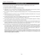
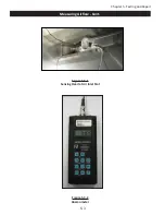
Страница 43: ...5 3 Chapter 5 Testing and Repair Measuring Airflow Cont Figure 5 3 1 Sensing Head at Air Inlet Slot Figure 5 3 2 Anemometer ...

Страница 44: ...0 INCH MIN NO REAR WALL MP 24 INCH MIN W REAR WALL MP 24 INCH MIN NO REAR WALL BB 12 INCH MIN DOUBLE VALUE SIDE LP 12 INCH MIN W REAR WALL LP 12 INCH MIN NO REAR WALL FACETED CHAMFERED OR ROUND FRONT SQUARE FRONT WITH 6 TO 12 INCH SUPER CAP LIP BB 30 INCH MIN DOUBLE VALUE SIDE SECTION VIEW 104 110 131 131 124 137 171 171 157 171 211 218 137 144 184 198 218 231 225 245 137 151 178 191 147 147 170 1...

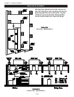
Страница 45: ...s A With Gaylord Plenum Boxes and ceiling diffusers 1 Gaylord Plenum Boxes Model PBW shall be located immediately in front of the Ventilator a minimum of 18 from the lower lip of the Ventilator to the discharge surface of the Plenum Box Refer to Figures 5 6 1 and 5 6 2 2 The amount of make up air delivered through the Gaylord Plenum Box s shall be between 90 and 100 of the values shown on Gaylord ...

Страница 46: ...t in proper cap ture and containment at the Ventilator and enact the Gaylord Capture Performance Guarantee If jobsite conditions cannot accommodate these guidelines consult Gaylord Industries for alternative design Figure 5 6 1 Plan View Typical Kitchen Figure 5 6 2 Section View Typical Kitchen ...

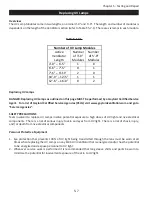
Страница 47: ...t TESTING AND REPAIR Replacing UV Lamps Overview The UV Lamp Modules come in two lengths a nominal 3 0 and 5 0 The length and number of modules is dependent on the length of the Ventilator section refer to Table T 5 13 1 The number of lamps used is dependent on the type of cooking equipment the Ventilator is covering Table T 5 13 1 Replacing UV Lamps DANGER Replacing UV Lamps as outlined on this p...

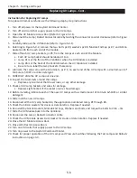
Страница 48: ...d of the UV Lamp with a small amount of Formula G 510EF or similar detergent 9 CAREFULLY slide the UV Lamp out one end 10 Inspect the Grommets around the Lamps Replace any Grommet that show cracks or any other damage 11 Check all UV Lamp Sockets and wires for damage Replace Light Sockets if the socket or wire show damage 12 Before installing lubricate each of the new UV Lamps with a small amount o...

Страница 49: ...s Lights AutoStart Sensor Static Tap Opening UV Lamp Module UV Lamps Extractor Extractor Access Door 1 4 20 Bolt Washer Module End Cap Silicon Gasket UV Lamp Socket Long Wire End Wire Not Illustrated Grommet Washers Nuts Front of UV Lamp Module Conduit Tube Pinned Receptacle Rear of UV Lamp Module Lamp 1 9 10 8 2 5 6 7 8 11 Lamp 2 Lamp 4 Lamp 5 Lamp 3 Lamp 6 ...

Страница 50: ...inadvertent exposure of the skin to UV light Instructions for Replacing UV Lamp Sockets Individual Method To replace UV Lamp Sockets carefully use the following step by step instructions 1 Turn off all power to the Gaylord Command Center 2 Turn off all circuits that supply power to the UV Lamps 3 Open the UV Module Access Door Refer to Figure 5 9 1 4 Disconnect the Lamp Ballast Connector Cable by ...

Страница 51: ... cut Long Wire to the socket end of the new UV Socket Long Wire and pull it through the conduit wire way Refer to Figure 5 13 3 18 Slide the UV Sockets onto the Lamp at both ends 19 Check the Silicon Gaskets for cracks or deterioration Replace if needed 20 Re install the Silicon Gaskets Module End Caps Washers and bolts and torque the bolts to 20 in lbs 21 Slide the UV Module back into the Ventila...

Страница 52: ...nnected to the base of a Pinned Receptacle Instructions To replace all UV Lamp Sockets with a wiring harness carefully use the following step by step instructions 1 Turn off all power to the Gaylord Command Center 2 Turn off all circuits that supply power to the UV Lamps 3 Open the UV Module Access Door 4 Disconnect the Lamp Ballast Connector Cable by twisting the connector counter clockwise refer...

Страница 53: ... if needed 16 Re install the Module End Caps with gasket washers and bolts and torque the bolts to 20 in lbs 17 Slide the UV Module back into the Ventilator 18 Reconnect the Lamp Ballast Connector Cable 19 Check the UV Module Access Door Gasket for cracks or deterioration Replace if needed 20 Close the UV Module Access Door 21 Turn on all circuits that supply power to the UV Lamps 22 Turn on power...

Страница 54: ... always serves the left UV Lamp Module and the Rear Ballast Board always serves the right UV Lamp Module So for example if the Ventilator has two Lamp Modules the Front Ballast Board Plate would have two Ballast Boards and the Rear Ballast Board Plate would also have two Bal last Boards The Ballast Boards are numbered 1 2 and 3 Ballast Board number 1 serves Lamp number 1 and 2 Ballast Board number...

Страница 55: ... on all circuits that supply power to the UV Lamps 12 Turn on power to the Gaylord Command Center 13 Check to make sure both Green lights are on Replacing UV Ventilation Control Board The UV Ventilation Control Board Refer to Figures 5 19 2 and 5 22 2 monitors all the Safety Interlock Pres sure Switches If the Safety Interlock Pressure Switches are in a normal operational condition a signal is sen...

Страница 56: ...jury and or death from live electrical components 1 Turn off all power to the Gaylord Command Center 2 Turn off all circuits that supply power to the UV Lamps 3 Remove the UV Ballast Box Access Cover 4 Disconnect the wires from the terminal block 5 Remove the 4 screws from the holding bracket and remove the fan 6 Install a new fan in the reverse order 7 Inspect the UV Ballast Box Access Box Access...

Страница 57: ...he switches There is a risk of shock injury and or death from contact with live electrical components CAUTION Verify that the SPADE CONNECTORS ARE IN PLACE PRIOR TO ANY ADJUSTING as illustrated in Figure 5 19 1 If Not proceed to Spade Connector not in Place Procedure PRIOR to Starting Site Conditions The Kitchen Exhaust system is to be fully balanced All Doors and win dows to be closed and sealed ...

Страница 58: ...Repeat this process for Pressure Switch B The Pressure Switches are now set 8 Replace the pressure switch covers 9 Briefly secure the Ballast Box Access Cover It must be in place to maintain proper pressurization in the Ballast Box enclosure 10 Test the System Remove the XGS Extractor s at one end of the Ventilator The UVi SYSTEM ON light s must DEACTIVATE and the UV Lamps shut off shut off immedi...

Страница 59: ...witches CAUTION VERIFY SPADE CONNECTOR IS IN PLACE PRIOR TO ADJUSTMENT IF IT IS NOT FOLLOW SPADE CONNECTOR NOT IN PLACE PROCEDURE ON PAGE 5 18 Figure 5 19 2 Ventilation Control Board COVER SCREW SPADE CONNECTOR ADJUSTMENT DIALS A B GREEN LED LIGHTS TERMINALS L3 AND L4 TERMINAL 6U ...

Страница 60: ...Repair UV Ballast Box Cont Figure 5 20 1 High Temperature Shutdown Controller Figure 5 20 2 UV Ballast Box PRESSURE SWITCHES VENTILATION CONTROL BOARD BALLAST BOARD VENTILATION FAN MESH FILTER HIGH TEMPERATURE SHUTDOWN CONTROLLER ...

Страница 61: ...g insulation or other material Corrective action Remove any building insulation from the inlet of the louvers 4 Building insulation has been placed over the top of the Ballast Box Corrective action Cut a rectangular opening in the insulation the size of the Ballast box and slide it down around the sides of the box Tape the insulation down so it will not interfere with the openings 5 The cooking eq...

Страница 62: ...5 22 Chapter 5 Testing and Repair UV Ballast Box Cont Figure 5 22 1 Ballast Board Figure 5 22 2 Ventilation Control Board Figure 5 22 3 Safety Interlock Pressure Switch ...

Страница 63: ...emble in reverse order f If the diaphragm looks worn or defective it should be replace with a Solenoid Valve Repair Kit Refer Chapter 6 Ventilator Parts If solenoid valve sticking is a recurring problem it indicates that foreign material in the water supply line is escaping through the line strainer located in the Wash Control Cabinet The screen in the line strainer should be removed checked for h...

Страница 64: ...Cont Solenoid Valve Not Opening Cont f Slide the wires from the new Solenoid through the conduit and into the junction box and connect the wires g Slide the new Solenoid onto the coil stem h Install the Solenoid Retainer Figure 5 24 1 Water Solenoid Valve VALVE HOUSING ...

Страница 65: ...ton The Extrac tor Wash will come on for 60 seconds While on open each of the Extractor Access Doors individually and observe each nozzle for spraying Note For instructions to access the EXTRACTOR WASH TEST button refer to the Operation Maintenance Installation Manual for the Command Center 4 To test the Plenum Wash it is first necessary to remove all the XGS Extractors 5 Close all Extractor Acces...

Страница 66: ...ights 20326 for 48 Fluorescent Lights 20327 7 PC No Description Gaylord Part No Illustration 1 Extractor Model XGS Size 11 H x 16 L 76044 2 Extractor Model XG SPA Spark Arrester Size 11 H x 16 L 76045 3 100 Watt Surface Mounted Light Lens 10119 4 12 x 12 Recessed Incandescent Light Lens and Retainer 13211 5 48 Long Recessed Fluorescent Light Lens and Retainer 10112 6 36 Long Recessed Fluorescent L...

Страница 67: ...t 250 degrees F 18465 2 Ventilator Exhaust Duct Collar Thermostat 15 Long NC Contacts Factory set at 250 degrees F Note For ELXC BBC Series Only 18466 3 Static Tap 19545 Table T 6 2 1 Parts Ventilator Cont 4 Damper Control Motor 24 Volts For GFBD and GEBD Model Dampers 19176 5 Spray Nozzle For Extractor Wash 20329 6 Spray Nozzle For Plenum Wash Pack of 2 10303 ...

Страница 68: ... Gaylord Part No Illustration 1 Autostart Sensor new style 20319 2 Autostart Sensor old style 76004 3 Autostart Controller complete with box 20317 4 Autostart Controller only No box provided 20318 Table T 6 3 1 Parts Ventilator Cont 4 No box provided 20318 6 3 ...

Страница 69: ...des Lamps 76058 3 3 0 Lamp single lamp 20269 4 5 0 Lamp single lamp 20270 5 UV Modual Ballast Connector 76069 Table T 6 4 1 Parts UV Ventilator 6 UV Status Lamp Green 19725 7 UV Status Lamp Yellow 19724 8 UV Status Lamp Blue 19723 Gasket for UV Module Access Doors 3 0 Module 20170 5 0 Module 20171 Lift Turn Latch for UV Module Access Door 19351 10 9 20138 Module ...

Страница 70: ...amp single lamp each 20269 5 0 Lamp single lamp each 20270 9 Panel Mount Pinned Receptical 20 27 1 20283 Lamps sold individually Table T 6 5 1 Parts UV Lamp Module Not Illustrated er 6 Parts UV Ventilator Parts Description Gaylord Part No Illustration UV Module 3 0 6 Lamps Includes Lamps 76057 UV Module 5 0 6 Lamps Includes Lamps 76058 3 0 Lamp single lamp 20269 5 0 Lamp single lamp 20270 UV Modua...

Страница 71: ...ket with 76 Halogen Free Wire and Connector Pin Shipped Loose 19799 Complete Single Pin UV Lamp Socket wiring harness for 6 Lamp Modules Includes the short and long Lamp Socket wires pre wired Parts UV Lamp Module cont Table T 6 6 1 1 short and long Lamp Socket wires pre wired to the base of the Panel Mount Base Receptical For 3 0 Lamp Module 20412 For 5 0 Lamp Module 20413 5 UV Module 3 0 6 Lamp ...

Страница 72: ...ion Gaylord Part No Illustration 1 Ventilation Fan 19430 UV Ballast Board complete For 3 0 6 Lamp Module 76063 For 5 0 6 Lamp Module 76065 Parts UV Ballast Box Table T 6 7 1 2 3 UV Ventilation Control Board 20100 4 Contactor 30529 UV Ballast Board complete 22472 ...

Страница 73: ...2 UV Pressure Switch 20146 3 Pressure Switch Pressure Release Tube 20174 NOT ILLUSTRATED Parts UV Ballast Box Cont Table T 6 8 Gasket for UV Ballast Box Access Cover 11 1 2 x 20 20173 16 x 16 20172 1 4 20 Chrome Acorn Nut for UV Ballast Box Cover 10766 Bonded Sealing Washer 20140 4 5 Vacuum Release Tube ...

Страница 74: ...7 1 Chapter 7 Wiring Diagrams ELXC GBD with AUTOSTART ...

Страница 75: ...7 2 Chapter 7 Wiring Diagrams ELXC GFBD with AUTOSTART ...

Страница 76: ...7 3 Chapter 7 Wiring Diagrams ELXC GBD UVi with AUTOSTART ...

Страница 77: ...7 4 Chapter 7 Wiring Diagrams ELXC GFBD UVi with AUTOSTART ...

Страница 78: ...listing Hanging the Ventilator Use the following guidelines for hanging the Gaylord Ventilator 1 The maximum section length of a Gaylord Ventilator is 16 0 Ventilators longer than 16 0 are made up of multiple sections 2 The weight of the Ventilator is shown on the Gaylord Submittal Drawings 3 Each Ventilator section has a full length Rear Mounting Bracket at the rear for bolting to the wall and or...

Страница 79: ...en installing Ventilators incorporating a UV system ELXC UVi Series do not cover the UV Ballast Box mounted on top of the Ventilator with building insulation Covering the Ballast Box inlet and outlet ventilation openings will cause the box to overheat which could result in failure of electrical components Covering the Ballast Box with insulation will void the Ventilator and the Warranty Table T A ...

Страница 80: ...ight switch 6 Ventilators built in multiple sections have a flex conduit at the section breaks for interconnecting the light fixture J boxes The electrical contractor is responsible for making these connections Additional Electrical for Ventilators with a UV System Refer to the wiring diagrams on the Gaylord Submittal Drawings for specific wiring interconnections 1 The UV Lamp Modules are shipped ...

Страница 81: ...sys tem would be installed by a local Fire System contractor Use the following guidelines 1 Fire Extinguishing System furnished must be in accordance with the terms of its listing and the applicable NFPA or IFC codes and standards 2 Caution Fire extinguishing system piping installed on the Ventilator at jobsite should be coordinated with Gaylord Industries to ensure piping does not interfere with ...

Страница 82: ...A 5 Appendix A Page A 5 Installation Requirements cont Figure A 5 1 Typical Installation MAIN FEED PIPE ...

Страница 83: ...A 6 INTENTIONALLY LEFT BLANK ...

Страница 84: ...t Report page B 4 are used The UV Lamp Modules for ELX UVi Series are shipped by Gaylord Industries directly to the jobsite A Gaylord Authorized Representative or Agency will install the modules at the time of Start Up Pre Start Up Requirements Before a Gaylord Start Up can be performed the responsible contractor or dealer must have the Ventilator installed and operating The following is a check l...

Страница 85: ...are plumbed to the floor sink or other drain ____ Fire Extinguishing System installed and certified ____ All Gaylord XGS Extractors are installed in the Ventilator s For ELXC UVi Series Ventilators ____ There is a 208 250 VAC 50 60HZ Single Phase 20AMP circuit going to the Ballast Box on the top of each individual Ventilator section One power source will serve a two section Ventilator ____ If the ...

Страница 86: ...etailed in the ELXC Series Operation Maintenance and Installation Manual Record all readings in the chart below Record the Design CFM from the Gaylord Drawings or the Ventilator Nameplate If the installation includes a Plenum Box make up air system take velocity readings and record on the chart Make Up Air 1 When the Exhaust Fan is on the Make Up Air should be on Is the Make Up air on ____ Yes ___...

Страница 87: ...Check a Any water leaks ____ Yes ____ No b Detergent pump is primed and pumping ____ Yes ____ No c Water pressure is 40 psi Min to 80 psi Max ____ psi d Water temperature is 140 F Min to 180 F Max ____ F e Brand of detergent used ________________________________ Frequency and Length of Wash 1 Record the Equipment Duty and the Length of the Wash Cycle programmed in the Gaylord Command Center for ea...

Страница 88: ...rd Electric Fire Balancing Damper Test Damper Model GFBD 1 Caution Performing this test may set off the building fire alarm system and may notify the fire department Notify building management maintenance and disable the building alarm system is necessary 2 Ventilators with this model damper including a thermostat that when activated by high heat or fire closes the damper This test is also called ...

Страница 89: ...____________________________ Title ______________________________________________________ Date __________ Comments __________________________________________________________________________________________ __________________________________________________________________________________________ __________________________________________________________________________________________ ____________...

Страница 90: ...nstalled ____ Yes ____No 2 Open the UV Module Access Doors and slide in the UV Lamp Modules 3 Once installed connect the Lamp Ballast Connectors to the UV Lamp Modules 4 Close the UV Module Access Doors and latch UV Safety Interlock Test for Extractors 1 Set the Safety Interlock Pressure Switches in accordance with the Gaylord Installation Operation and Maintenance Manual Once the Pressure Switche...

Страница 91: ...the Gaylord Installation Operation and Maintenance Manual for ELXC and ELXC UVi Series Ventilators ____ CSA Initial 6 Provide a copy of the Gaylord Command Center Technical Manual ____ CSA Initial 7 Provide a copy of this UV Start Up Inspection and Test Report ____ CSA Initial Note to Operator You may obtain a free copy of the Gaylord Installation Operation and Maintenance Manual and the Gaylord C...

Страница 92: ... the United States all replacement parts furnished under this warranty shall be F O B Gaylord Industries Tualatin Oregon U S A The owner shall pay the necessary freight delivery charges and necessary labor for removal and installation of parts and any tariffs duties or taxes Component parts not manufactured by Gaylord Industries such as electrical switches solenoid coils relays etc shall be warran...

Страница 93: ...LATION COM OR CONTACT US AT GAYLORD INDUSTRIES 10900 SW AVERY STREET TUALATIN OREGON 97062 U S A Phone 503 691 2010 1 800 547 9696 Fax 503 692 6048 email info gaylordventilation com LOCAL SERVICE AGENCY FORM NO COPYRIGHT 2013 GAYLORD INDUSTRIES LITHO IN U S A FORM NO TM ELXC UVi Rev 07 0415 30926 COPYRIGHT 2015 GAYLORD INDUSTRIES LITHO IN USA ...

Отзывы: