background image

Instructions for DKC500ACL/DKC800ACL

www.gatexpertstore.com

15

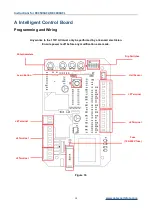
J5 Terminal

Hall Sensor

J3 Terminal

Dip Switches

Learn Button

Potentiometers

A Intelligent Control Board

Programming and Wiring

Any works to the 110V AC must only be performed by a licensed electrician.

Ensure power is off before any modifications are made.

Fuse

(10A 250V fuse)

J4 Terminal

J6 Terminal

J2 Terminal

Figure 16

Содержание DKC500ACL

Страница 1: ...Sliding Gate Opener User Manual DKC500ACL DKC800ACL Website www gatexpertstore com E mail sales gatexpertstore com...

Страница 2: ...eration When mounting and positioning this product please ensure the power cable is unplugged The motor cover will need to be removed to mount the motor to the mounting plate or directly to the concre...

Страница 3: ...e or replace for free 4 The malfunction and damages caused by incorrect use or man fault is not covered by this warranty CONTACT US E mail sales gatexpertstore com Please fill in the order information...

Страница 4: ...rocket and Chain Motor Alignment 10 Step 7 Limit Switch Stops 11 Step 8 Powering on 13 Step 9 Testing Travel and Limit Stops 14 A Intelligent Control Board 15 Programming and Wiring 15 DIP Switch Adju...

Страница 5: ...tates to the opposite direction This will give you an understanding of the way how the opener moves the gate Figure 2 Note Ensure that the gate opener is unplugged before proceeding with installation...

Страница 6: ...nd prevent injury to person or damage to property Instruct all users about the control systems provided and the manual opening operation in case of emergency Ensure that the power cable is connected t...

Страница 7: ...No Picture Name Quantity 1 Motor 1 2 Manual Release Keys 2 3 Remote Controls 2 4 Mounting Accessories Box 1 4 1 Sprocket Cover 1 4 2 Chain Including 2 Chain Links 6m 4 3 Tie Rod 2 4 4 Square Screw 4 4...

Страница 8: ...t M8 4 Flat Washer 8 2 Spring Washers 8 2 4 11 Inner Hexagon Head Bolt M6X20 4 4 12 Hexagon Head Bolt M8X40 4 4 13 Nut M6 16 Nut M8 16 4 14 Flat Washer 6 16 Flat Washer 8 16 4 15 Spring Washers 6 16 S...

Страница 9: ...20min Recording of up Remote Controls Standard control board 25 Intelligent control board 40 Remote Frequency 433 92 MHz Working Temperature 20 C 70 C Package Weight 16 42KG 16 5KG Installation Before...

Страница 10: ...s not plugged in at any stage before Step 8 Step 1 Gate Preparation Ensure that the sliding gate is correctly installed The gate is horizontal and level and the gate can glide back and forth smoothly...

Страница 11: ...e 6 Figure 6 Step 3 Removing Installing Motor Cover Unscrew the two cover screws located at each side of the motor cover Remove the rubber grommet below the limit switch Figure 7 Figure 7 Sprocket cov...

Страница 12: ...long x 350mm wide and a minimum depth of 200mm Standard requirement Ensure surface is level and parallel to the driveway Mounting Base Dimensions Figure 9 Step 5 Fitting Mounting Base and Motor Fit a...

Страница 13: ...tput sprocket and chain are correctly aligned Sprocket and chain should be centered as much as possible Take the motor away from mounting base Leave a space of 30cm from the motor to end of the chain...

Страница 14: ...rcumstances should the gate opener output sprocket carry any weight of the gate It is the task of the gate castors or wheels to carry the weight of the gate If the gate doesn t slide freely by hand ad...

Страница 15: ...g It is extremely dangerous that without or incorrect installation of the limit switch stops can cause crash of gate damage of internal structure of the motor moreover the gate may slide off the guide...

Страница 16: ...when setting the open position under power Fit limit switch stop onto the top of chain at the point where it meets the magnetic limit switch on the motor Tighten locking screws of limit switch stop T...

Страница 17: ...r has been fitted and fastened back onto the motor base Before powering up the gate opener make sure the gate can travel by hand in manual mode key unlocked Slide the gate to between the middle of the...

Страница 18: ...te frame is 10 15mm from closed gate end catch Testing the Open Position Press remote the sliding gate will begin to open The limit switch stop will hit the limit switch and the sliding gate will stop...

Страница 19: ...rminal Dip Switches Learn Button Potentiometers A Intelligent Control Board Programming and Wiring Any works to the 110V AC must only be performed by a licensed electrician Ensure power is off before...

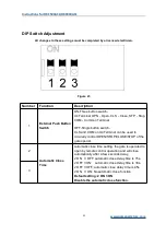
Страница 20: ...omatic Close Time Setting Automatic close time setting the gate is operated to open by remote control operation and will close automatically after a few seconds delay 3 OFF 4 ON automatic close delay...

Страница 21: ...ed Dip switch 5 is at the OFF position Do not turn Dip switch 5 to the ON position VR2 Brake Force Adjustment For adjusting brake force at the limit position during gate opening and closing This shoul...

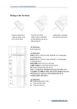
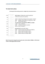
Страница 22: ...n Repeated Open Stop Close Terminal 4 Common Terminal for All External Control Push Button Terminal 3 External Stop Push Button Switch Terminal 2 External Open Push Button Switch Terminal 1 External C...

Страница 23: ...rection MOT2 Motor Terminal swap with MOT1 to change gate moving direction MOTCOM Motor Common Terminal LAMP L N Connection for warning lamp PE Motor and warning lamp earth Note If require to change t...

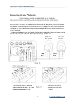
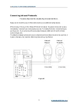
Страница 24: ...mmend the use of infrared photocells as an additional safety feature While closing if the ray of the Infrared Photocell is blocked the gate will stop and reverse immediately to protect user and proper...

Страница 25: ...l Figure 21 Remote Control Learning Remove motor outer cover and continue to remove the transparent PCB cover press the button S1 on the control board until the LEARN indicator light turns on then rel...

Страница 26: ...Programming and Wiring Any works to the 110V AC must only be performed by a licensed electrician Ensure power is off before any modifications are made Fuse 10A 250V fuse Dip Switches LEARN Button Moto...

Страница 27: ...e button switch CLS and COM on X4 Terminal can be used to circularly control OPEN STOP CLOSE STOP of the gate opener 2 Automatic Close Time Automatic close time setting the gate is operated to open by...

Страница 28: ...h and Photocell Switch Additional accessories sold separately 24VDC Positive Power Supply for Accessories 24VDC GND Negative Power Supply for Accessories GND LR Photocell Input N C If no photocell con...

Страница 29: ...wire X2 Terminal PE Earth V Common Terminal of Motor U Motor Terminal Switch SW1 will change gate moving direction W Motor Terminal Switch SW1 will change gate moving direction Note If require to chan...

Страница 30: ...hotocell is blocked the gate will stop and reverse immediately to protect user and property security To install photocells connect wiring as per Figure 24 You must remove the wire jumper between GND a...

Страница 31: ...n the remote control Single Button Mode Remote Control Figure 26 Remote Control Learning Remove the motor outer cover and continue to remove the transparent PCB cover press the button AN1 on the contr...

Страница 32: ...en the LED2 turns off all previously paired remote controls will be deleted Maintenance The gate should be checked every month to make sure it operates normally For the sake of safety each gate is sug...

Страница 33: ...ensure the wiring is correct and the photocell status is N C 2 Ensure that the photocell mounting position can be mutually aligned 3 Remove the obstacle 4 Reduce the sensitivity of obstacle 5 Replace...

Страница 34: ...Instructions for DKC500ACL DKC800ACL www gatexpertstore com 30 Drawing and Measurements Figure 27...

Отзывы: