
CHAPTER 3: Replacing notebook components
92
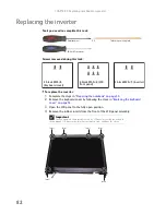
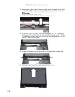
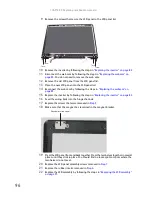
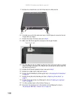
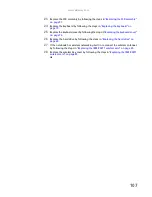
8
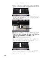
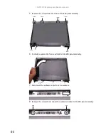
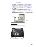
Detach the LCD cable from the system board. Make sure that you grasp the plastic
connector carefully and pull to unplug the LCD video cable from the notebook.
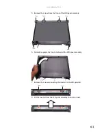
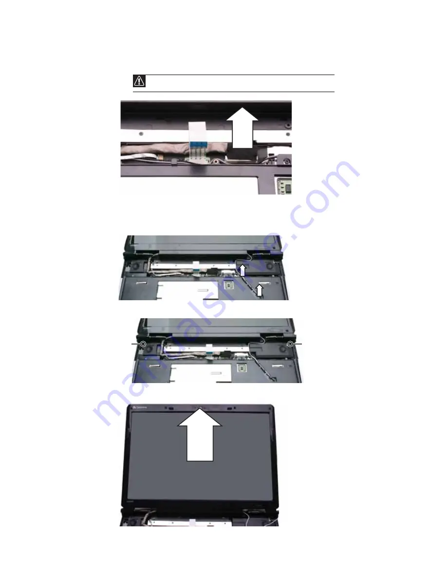
9
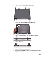
Taking care to note the cables’ routing and positions as they are installed from
Gateway, pull the antenna cables out from under the system board, then slide the
antenna cables and LCD cables out from under the retaining clips. Remove any tape
that may be securing the cables.
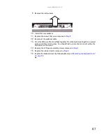
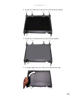
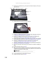
10
Remove the screws on the top that secure the LCD panel hinge to the chassis.
11
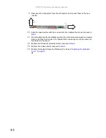
Lift the LCD panel assembly up and away from the notebook.
Caution
The LCD video cable connector is fragile.
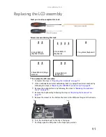
Screw
Screw
Содержание MG1
Страница 1: ... MG1 SERVICEGUIDE ...
Страница 6: ...Contents iv Microsoft Windows Vista Environment Test 176 Appendix C Online support information 179 ...
Страница 11: ...5 System block diagram ...
Страница 42: ...CHAPTER 1 System specifications 36 ...
Страница 43: ...CHAPTER2 37 System utilities BIOS Setup Utility BIOS flash utility Removing a password lock ...
Страница 56: ...CHAPTER 2 System utilities 50 ...
Страница 167: ...CHAPTER5 161 Connector locations System board top connectors System board bottom connectors ...
Страница 169: ...CHAPTER6 163 FRU Field Replaceable Unit list Introduction Exploded diagram FRU list ...
Страница 178: ...CHAPTER 6 FRU Field Replaceable Unit list 172 ...
Страница 179: ...APPENDIXA 173 Model definition and configuration Information not available at time of printing ...
Страница 181: ...APPENDIXB 175 Test compatible components Introduction Microsoft Windows Vista Environment Test ...
Страница 185: ...APPENDIXC 179 Online support information ...
Страница 190: ...Index 184 ...
Страница 191: ......
Страница 192: ...MAN GODZILLA SVC GDE R1 07 08 ...