

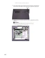
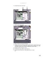
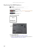

CHAPTER 3: Replacing notebook components
60
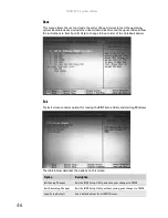
6
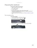
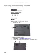
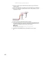
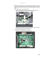
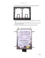
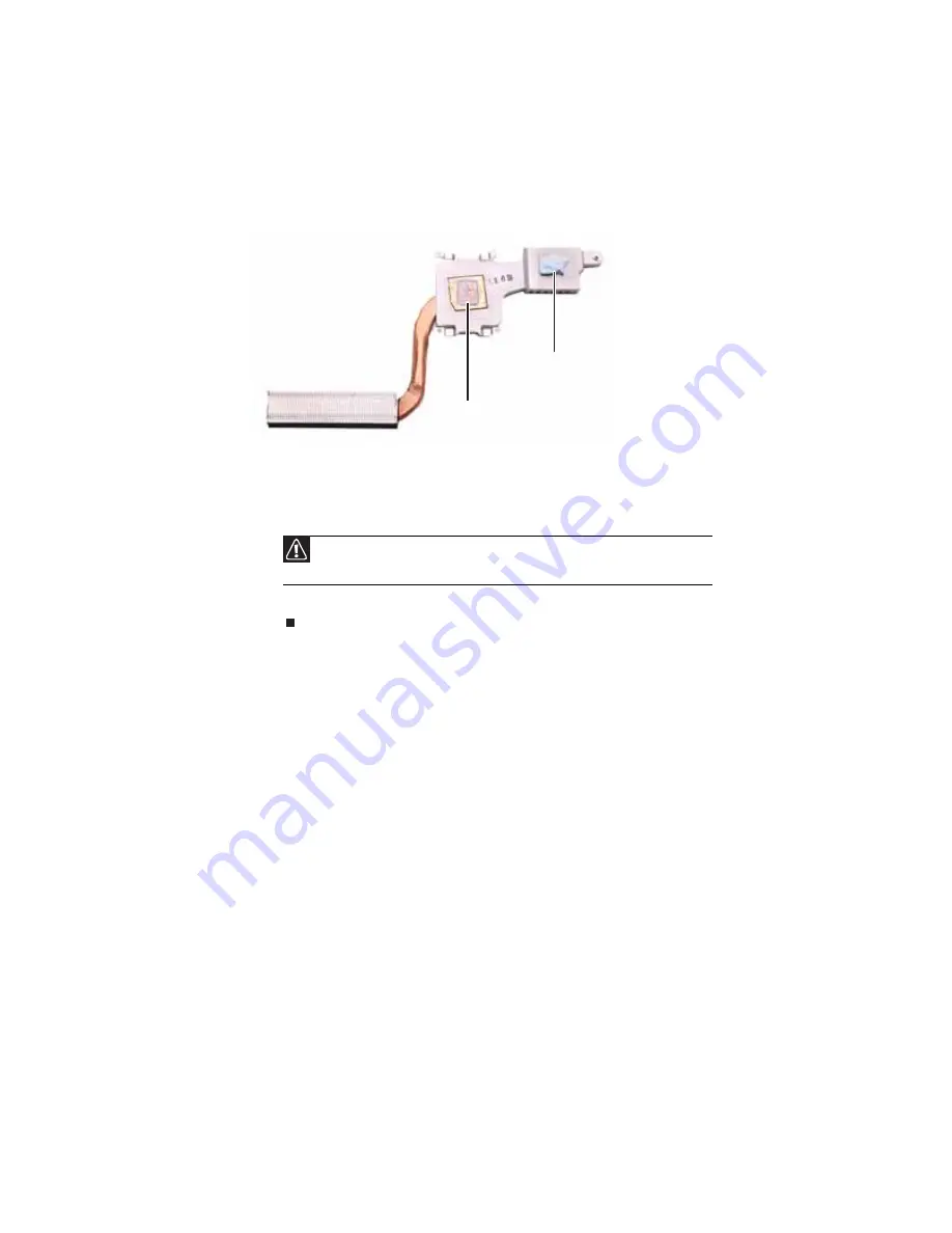
Remove any thermal grease residue from the processor using a soft cloth and
isopropyl alcohol.
7
Place new thermal grease on the processor. Use only enough to cover the CPU die.
8
Make sure a thermal pad is placed between the main cooling assembly and other
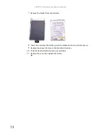
components as shown.
9
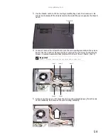
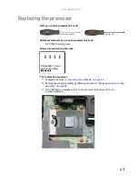
Insert the new main cooling assembly into the notebook.
10
Tighten the screws that secure the main cooling assembly to the system board. Use
the numbers stamped in the metal next to each screw and tighten the screws in
numerical order (start with 1, then 2, then 3, then 4, then 5).
11
Replace the cooling assembly bay cover, then tighten the cover screws.
Caution
When tightening the main cooling assembly’s screws into the numbered
holes, tighten them in numerical order.
Thermal
pad
Thermal grease
Содержание MG1
Страница 1: ... MG1 SERVICEGUIDE ...
Страница 6: ...Contents iv Microsoft Windows Vista Environment Test 176 Appendix C Online support information 179 ...
Страница 11: ...5 System block diagram ...
Страница 42: ...CHAPTER 1 System specifications 36 ...
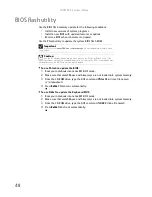
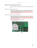
Страница 43: ...CHAPTER2 37 System utilities BIOS Setup Utility BIOS flash utility Removing a password lock ...
Страница 56: ...CHAPTER 2 System utilities 50 ...
Страница 167: ...CHAPTER5 161 Connector locations System board top connectors System board bottom connectors ...
Страница 169: ...CHAPTER6 163 FRU Field Replaceable Unit list Introduction Exploded diagram FRU list ...
Страница 178: ...CHAPTER 6 FRU Field Replaceable Unit list 172 ...
Страница 179: ...APPENDIXA 173 Model definition and configuration Information not available at time of printing ...
Страница 181: ...APPENDIXB 175 Test compatible components Introduction Microsoft Windows Vista Environment Test ...
Страница 185: ...APPENDIXC 179 Online support information ...
Страница 190: ...Index 184 ...
Страница 191: ......
Страница 192: ...MAN GODZILLA SVC GDE R1 07 08 ...