Gateway MG1 Скачать руководство пользователя страница 188

Index

182

eSATA

jack  

18

Ethernet

jack  

17

ExpressCard

controller  

10

external CD-ROM drive check  

144

external monitor  

18

24

EZ Pad touchpad

See 

touchpad

F

fan  

17

18

features  

2

files

opening  

31

fingerprint

enrolling  

26

fingerprint reader

control center  

28

locating  

20

password bank  

29

tutorial  

26

using  

25

Firewire port  

17

flash utility  

48

Fn key  

23

folders

opening  

31

function keys  

23

H

hard drive

bay  

19

indicator  

22

HDMI (TV) out jack  

17

HDMI port  

24

headphone jack  

17

Help button  

34

Hybrid Sleep

mode  

24

system key  

24

I

i.Link port  

17

IEEE 1394 port  

17

indicators

See 

status indicators

Instant on Audio  

32

Instant on Video  

32

intermittent problems  

159

Internet chat program  

33

J

jacks

See 

connections

jumper and connector locations

top view  

162

K

Kensington cable lock

lock slot  

16

key combinations  

23

keyboard

buttons  

23

controller  

9

features  

23

keys  

23

locating  

20

USB port  

16

17

keyboard or auxiliary input 

device check  

145

keys

application  

23

arrow  

23

brightness  

25

directional  

23

Fn  

23

function  

23

Hybrid Sleep  

24

LCD brightness  

25

LCD/CRT  

24

navigation  

23

numeric keypad  

23

Sleep  

24

system  

23

system key combinations  

23

toggle display  

24

Windows  

23

wireless Ethernet  

24

L

latch

battery  

19

LCD panel release  

16

LCD panel

release latch  

16

switching display  

24

LCD/CRT system key  

24

lock

Kensington cable  

16

M

Media Center  

32

memory

bay  

19

memory card reader

controller  

10

locating  

17

supported cards  

10

memory check  

145

microphone

built-in  

21

jack  

17

modem

cable  

17

chipset  

12

DSL  

17

jack (dial-up)  

18

monitor

port  

18

using  

24

mouse

USB port  

16

17

moving

pointer  

31

screen objects  

31

multimedia panel  

20

32

mute button  

25

32

muting sound  

25

32

N

navigation keys  

23

network jack  

17

Num Lock

status indicator  

22

system key  

23

numeric keypad

status indicator  

22

using  

23

O

opening

files  

31

folders  

31

LCD panel  

16

notebook  

16

programs  

31

shortcut menu  

31

P

password bank  

29

pointer

Содержание MG1

Страница 1: ... MG1 SERVICEGUIDE ...

Страница 2: ...http csd acer com tw Copyright 2008 Gateway Inc All rights reserved Gateway Gateway Country the Gateway stylized logo and the black and white spot design are trademarks or registered trademarks of Gateway Inc in the United States and other countries All other brands and product names are trademarks or registered trademarks of their respective companies PRINTED IN TAIWAN Date Chapter Updates ...

Страница 3: ...8 Video subsystem 8 Keyboard 9 Pointing device 9 Memory card reader 10 ExpressCard 10 Audio 10 Wired LAN 11 Bluetooth 11 Wireless LAN 11 Modem 12 USB 12 Buttons Indicators Ports 13 Fingerprint reader 13 Camera 13 Fans 14 Battery 14 Power supply 15 Power savings 15 Notebook product tour 16 Front 16 Left 16 Right 17 Back 18 Bottom 19 Keyboard area 20 LCD panel 21 Using the status indicators 22 Using...

Страница 4: ...ing memory modules 56 Replacing the main cooling assembly 58 Replacing the processor 61 Replacing the IEEE 802 11 wireless card 63 Replacing the CMOS battery 66 Replacing the hard drive 69 Replacing the DVD drive 73 Replacing the keyboard cover 76 Replacing the keyboard 79 Replacing the inverter 82 Replacing the webcam 85 Replacing the lid latches 88 Replacing the LCD assembly 91 Replacing the LCD...

Страница 5: ...es 148 No beep error messages 150 Phoenix BIOS beep codes 151 Symptom to FRU error messages 156 LCD 156 Power 156 ExpressCard 157 Memory 157 Sound 157 Power management 157 Devices 158 Keyboard and touchpad 158 Modem 159 Intermittent problems 159 Undetermined problems 159 Chapter 5 Connector locations 161 System board top connectors 162 System board bottom connectors 162 Chapter 6 FRU Field Replace...

Страница 6: ...Contents iv Microsoft Windows Vista Environment Test 176 Appendix C Online support information 179 ...

Страница 7: ...CHAPTER1 1 System specifications Preface Features System block diagram Hardware specifications and configurations Notebook product tour ...

Страница 8: ...ble on your regional web or channel If for whatever reason a part number change is made it may not be noted in this printed service guide Acer authorized Service Providers Your Acer office may have a different part number code to those given in the FRU list of this printed service guide You use the list provided by your regional Acer office to order FRU parts for repair and service of customer mac...

Страница 9: ...bandwidth Digital Content Protection support Storage subsystem Industry standard 2 5 60 120GB 9 5mm height hard disk drive Optical drive options Blu ray Disc DVD Super Multi double layer drive DVD Super Multi double layer drive DVD CD RW combo drive 5 in 1 card reader supporting Secure Digital SD MultiMediaCard MMC Memory Stick MS Memory Stick PRO MS PRO xD Picture Card xD Input devices 103 key ke...

Страница 10: ...n jack for AC adapter ExpressCard 54 slot Fingerprint reader optional 5 in 1 card reader SD MMC MS MS PRO xD HDMI port with HDCP support optional Kensington lock slot Environment Operating 32 F to 90 F 0 C to 35 C Non operating 4 F to 140 F 20 C to 60 C Humidity non condensing Operating 10 to 90 Non operating 5 to 95 ...

Страница 11: ...5 System block diagram ...

Страница 12: ...GL40 PM45 ICH9M ICH9ME VGA Intel Crestline GM Nvidia NV8E GT NB9E GT LAN RealTek RTL8111C GR Marvell 88E8057 USB 2 0 Please provide Super I O controller Please provide Modem Agere Delphi AM5 MDC 1 5 form factor Bluetooth Please provide Wireless 802 11 Foxconn T60H928 Intel WiFi Link 5100 Intel Golan Intel Kedron Marvell WN6500M Marvell WN6300M Realtek RTL8187 ExpressCard Please provide Memory Card...

Страница 13: ...SB Specification 1 1 2 0 IEEE 1394 1 0 USB 1394 CD ROM Boot Up support PC Card Standard 1995 PCMCIA 3 0 Compliant Device IrDA 1 0 Support HD audio WfM 2 0 PXE 2 1 Preboot Execution Environment PXE 2 1 Boot Integrity Service Application Program Interface BIS 1 0 PC2002 2005 compliant Intel Enhanced Speedstep Technology ASF 2 0 TPM v1 2 AHCI support iAMT 4 0 or later for Intel platform BIOS password...

Страница 14: ...MM Supports maximum memory size 4 GB 8 GB Supports SO DIMM type DDR 2 Synchronous DRAM DDR 3 Synchronous DRAM Supports SO DIMM Speed 533 667MHz DDR 2 800 1066MHz DDR 3 Supports SO DIMM voltage Please provide Supports SO DIMM package 200 pin SO DIMM Memory module combinations You can install memory modules in any combinations as long as they match the above specifications Item Specification Chipset...

Страница 15: ...ibrant Color Temperature Correction LCD Overdrive High Quality Real Time video recording Best quality 10 bit display pipeline NVIDIA nView Multi Display Technology SmartDimmer Technology Integrated HDMI support Support for integrated HDCP NVIDIA Digital Vibrance Control Technology Integrate HDTV encoder Dual 400MHz RAMDACs Core voltage Please provide Item Specification Keyboard controller Winbond ...

Страница 16: ...er Please provide Supports card type Type 54 Number of slots One Access location Right panel Item Specification Audio Controller SigmaTel STAC9205 Conexant CX2056 15Z Audio onboard or optional Built in Mono or Stereo Stereo Resolution Ten DAC channels support 16 20 24 bit PCM format for 7 1 sound playback plus 2 channels of independent stereo sound output multiple streaming through the front panel...

Страница 17: ...connector location Left side Features Integrated 10 10 BASE T transceiver PCIe v1 1 compliant Wake on LAN support meeting ACPI requirements Item Specification Chipset Please provide Data throughput 2 1 Mbit s Protocol Bluetooth 2 0 Interface USB board level Connector type Wireless via Bluetooth protocols Item Specification Chipset Foxconn T60H928 Intel WiFi Link 5100 Intel Golan Intel Kedron Marve...

Страница 18: ...bis V 42 LAPM and MNP 2 4 error correction V 44 V 42bis and MNP 5 data compression Send and receive rates up to 14400 bps support ITU T V 17 V 29 V 27ter and V 21 Ch2 fax TIA EIA 602 Standard for AT command set and Fax TIA EIA 578 Class 1 command set Interface RJ11 Item Specification Chipset Please provide USB compliancy level 2 0 OHCI USB 1 1 and USB 2 0 host controller Number of USB ports 3 Loca...

Страница 19: ...splay VGA port Modem RJ11 optional Ethernet RJ45 IEEE1394 eSATA Headphone SPDIF Audio Out Microphone in DC in jack for AC adapter ExpressCard 54 slot Fingerprint reader optional 5 in 1 card reader SD MMC MS MS PRO xD HDMI port with HDCP support optional Item Specification Model UPEK TCS4BB Interface 8 bit parallel SPI Resolution High definition 192 4 pixel array Technology CMOS active capacitive p...

Страница 20: ...On Off Software Gateway Camera Assistant CPU Temperature Fan Speed rpm Acoustic Level dBA Please provide Please provide Please provide Item Specification Vendor Dyna Sanyo Simplo Battery Type Li ion Pack capacity 5772mAH 8658mAH Number of battery cell 6 or 9 Package configuration 3 cells in series 2 series in parallel 3 cells in series 3 series in parallel Normal voltage 11 1V Charge voltage 12 6V...

Страница 21: ...f completely Soft Off G2 S5 OS initiated shutdown All devices in the notebook are turned off completely Working G0 S0 Individual devices such as the CPU and hard disc may be power managed in this state Suspend to RAM S3 CPU set power down VGA suspend PCMCIA suspend Audio power down Hard drive power down Optical drive power down Super I O low power mode Save to Disk S4 Also called Hibernation mode ...

Страница 22: ...ss network switch Turn the optional IEEE 802 11 wireless network radio and optional Bluetooth radio on or off Warning Radio frequency wireless communication can interfere with equipment on commercial aircraft Current aviation regulations require wireless devices to be turned off while traveling in an airplane IEEE 802 11 and Bluetooth communication devices are examples of devices that provide wire...

Страница 23: ...ture Card cards IEEE 1394 port optional Plug an IEEE 1394 also known as Firewire or i Link device such as a digital camcorder or MP3 player into this optional 4 pin IEEE 1394 port Express Card slot Insert one Type 54 Express Card into this slot Headphone jack Plug amplified speakers or headphones into this jack The built in speakers are turned off when speakers or headphones are plugged into this ...

Страница 24: ...y become hot enough to harm your skin Caution Do not block or insert objects into these slots If these slots are blocked your notebook may overheat resulting in unexpected shutdown or permanent damage to the notebook Caution Provide adequate space around your notebook so air vents are not obstructed Do not use the notebook on a bed sofa rug or other similar surface Power connector Plug the AC adap...

Страница 25: ...ovides power when the notebook is not plugged into AC power Battery lock Slide to unlock the battery Customer Care label Includes the Customer Care contact information Hard drive bay The hard drive s is are located in this bay Online Support Tech Support Phone Hours Model S No Battery latch Memory bay Battery lock Battery Customer care label Hard drive bay ...

Страница 26: ...nfigure the power button for Sleep Resume mode Multimedia panel optional Use to control playback of CDs and DVDs The panel includes a capacitive touch volume control Touchpad Provides all the functionality of a mouse Fingerprint reader optional Provides enhanced security Status indicators Inform you when a drive is in use or when a button has been pressed that affects how the keyboard is used Stat...

Страница 27: ...oIP calls Important The optional microphone is only available when purchased with the optional webcam Webcam optional Use to let others see who they are communicating with when making VoIP calls Webcam status indicator optional Turns on when the webcam is turned on Optional webcam status indicator Optional microphone Optional webcam ...

Страница 28: ...ndicators on Indicator Icon Description Wireless network LED on Optional wireless IEEE 802 11 radio is turned on LED off Optional wireless IEEE 802 11 radio is turned off Caps lock LED on Caps lock is turned on LED off Caps lock is turned off Num lock LED on Numeric keypad is turned on LED off Numeric keypad is turned off DVD drive LED on Drive is in use LED off Drive is not in use Hard drive LED ...

Страница 29: ...tion keys for different purposes See the program documentation to find out more about the function key actions System keys Press these colored keys in combination with the FN key to perform specific actions Navigation keys Press these keys to move the cursor to the beginning of a line to the end of a line up the page down the page to the beginning of a document or to the end of a document Numeric ...

Страница 30: ...or HDMI port on your notebook Both displays at the same time Turn the optional Bluetooth radio on or off Warning Radio frequency wireless communication can interfere with equipment on commercial aircraft Current aviation regulations require wireless devices to be turned off while traveling in an airplane Bluetooth communication devices are examples of devices that provide wireless communication Im...

Страница 31: ...ience The fingerprint reader is located between the left and right touchpad buttons Skip ahead one CD track or DVD chapter Increase the brightness of the display Decrease the brightness of the display Increase volume Decrease volume Mute the sound Press the key combination again to restore the sound Press and hold FN then press this system key To ...

Страница 32: ...orial 1 Click Start All Programs Protector Suite QL then click Fingerprint Tutorial 2 Click Next to proceed through the tutorial Enrolling your fingerprints Before you can use the features of the fingerprint reader you must enroll your fingerprints so your notebook can identify you To enroll your fingerprints 1 Click Start All Programs Protector Suite QL then click User Enrollment The Welcome scre...

Страница 33: ...al the Enrollment screen appears OR If you do not want to run the TouchStrip Tutorial click to uncheck the Run interactive tutorial check box then click Next The Enrollment screen appears 5 Click the button above the finger you are enrolling A new box appears with three empty circles in it 6 Swipe your finger A sample will be created and is indicated by a fingerprint icon in one of the circles ...

Страница 34: ... control how the fingerprint reader is used You can Add new fingerprints to the database Edit or delete fingerprints from the database Modify how fingerprints are used for logging onto the notebook Modify how the fingerprint reader is used for scrolling To use the Fingerprint Control Center 1 Click Start All Programs Protector Suite QL then click Control Center The Fingerprint Control Center opens...

Страница 35: ...eady enrolled finger over the sensor The fingerprint reader menu opens 4 Click Register 5 Click on the dialog box or Web site sign in box To log on to a registered Web site 1 Swipe your already enrolled finger over the sensor The fingerprint reader menu opens 2 Click Registered Sites then click the Web site you want to log onto 3 Your Internet browser opens and automatically logs you onto the Web ...

Страница 36: ... move your finger on the touchpad the pointer arrow on the screen moves in the same direction You can use the scroll zone to scroll through documents Use of the scroll zone may vary from program to program You can use the EZ Pad left and right buttons below the touchpad to select objects Touchpad Left button Right button Scroll zone ...

Страница 37: ...t a program or open a file or folder Position the pointer over the object Press the left button twice in rapid succession This action is called double clicking Access a shortcut menu or find more information about an object on the screen Position the pointer over the object Quickly press and release the right button once This action is called right clicking Move an object on the screen Position th...

Страница 38: ... Windows Vista Ultimate or the DVD player program Windows Vista Home Basic Play or pause the CD or DVD Stop playing the CD or DVD Skip back one CD track or DVD chapter Skip ahead one CD track or DVD chapter Mute the sound Press again to restore the sound Capacitive volume control Swipe your finger on the volume sensor strip to change the volume To increase volume move from the towards the To decre...

Страница 39: ...use the optional webcam with many of the available Internet chat programs to add video and audio to your chat session In addition by using the software included with the webcam you can take pictures or create video clips Webcam Status indicator Microphone ...

Страница 40: ...Button Icon Description Start camera Turns on the camera and opens the preview screen Effects Adds a decoration or border to your picture Properties Modifiespropertiessuchaszoom backlightcompensation brightness and contrast Settings Selects the position of the toolbar or modifies the picture video or audio settings Help Opens online help Important If you do not see the toolbar the Auto Hide settin...

Страница 41: ...apshot Take a picture of what is currently in the preview screen Video recording Create a video recording Audio recording Create an audio recording Functions Change a setting or access online help Resolution Change the size of the picture Mute Turn audio capture on or off Effects Add a decoration or border to your picture ...

Страница 42: ...CHAPTER 1 System specifications 36 ...

Страница 43: ...CHAPTER2 37 System utilities BIOS Setup Utility BIOS flash utility Removing a password lock ...

Страница 44: ...y To choose a menu use the left and right arrow keys To choose an item use the up and down arrow keys To change the value of a parameter press F5 or F6 A plus sign indicates the item has sub items Press ENTER to expand this item Press ESC while you are in any of the menu options to go to the Exit menu In any menu you can load default settings by pressing F9 You can also press F10 to save any chang...

Страница 45: ...aries by model features ordered and location Parameter Description System Time Sets the system time The hours are displayed in a 24 hour format System Date Sets the system date System BIOS Version Shows the version of the system BIOS CPU Type Shows the type of CPU installed in the notebook CPU Speed Shows the speed of the CPU installed in the notebook Total Memory Shows the total memory in the not...

Страница 46: ...f the USB devices work under MS DOS or CMOS SETUP Option Enabled or Disabled Extreme CPU Speed Specifies to speed of a GExtreme CPU SATA Mode Specifies the SATA controller mode Option IDE AHCI or RAID Quiet Boot Determines if the Summary Screen is disabled or enabled Enabled The Gateway logo is displayed and the Summary Screen is not displayed Disabled The Gateway logo is not displayed and the Sum...

Страница 47: ...d Clear or Set User Password Is Shows the setting of the User password Clear or Set Set Supervisor Password Press Enter to set the supervisor password When set this password protects the BIOS Setup Utility from unauthorizedaccess Theuser cannot enter the Setup Utility without entering this password Set User Password Press Enter to set the user password When a user passwordisset thispassword protec...

Страница 48: ...ite Protect Password on Boot Defines whether a password is required or not while the events defined in this group happened The sub options all require the Supervisor password for changes and should be grayed out if the User password was used to enter the Setup Utility Disabled or Enabled Caution When you are prompted to enter a password you have three tries before the system halts Don t forget you...

Страница 49: ...w Password field 4 Press ENTER After setting the password the value of User Password changes to Set 5 When you are done press F10 to save your password and exit the BIOS Setup Utility Removing a Password To remove a password 1 Press or to highlight Set Supervisor Password or Set User Password then press ENTER The Set Supervisor Password or Set User Password box opens 2 Type the current password in...

Страница 50: ... then press ENTER The Set Supervisor Password or Set User Password box opens 2 Type the current password in the Enter Current Password field then press ENTER 3 Type a password in the Enter New Password field Important If you enter an incorrect current password the screen displays the following Press ENTER then re enter the current password ...

Страница 51: ... displays the following 6 Press ENTER 7 When you are done press F10 to save your password and exit the BIOS Setup Utility Important If you do not enter the same new password and confirm new password the screen displays the following Press ENTER then re enter the new password and confirmation password ...

Страница 52: ...Help to change to boot order of the notebook devices Exit The Exit screen contains options for leaving the BIOS Setup Utility and starting Windows The table below describes the options on this screen Option Description Exit Saving Changes Exit the BIOS Setup Utility and save your changes to CMOS Exit Discarding Changes Exit the BIOS Setup Utility without saving your changes to CMOS Load Setup Defa...

Страница 53: ...www gateway com 47 Discard Changes Load previous values from CMOS for all SETUP items Save Changes Save your changes to CMOS Option Description ...

Страница 54: ...type the DOS command Phlash16 rom file name c x mode 3 4 Press ENTER Phlash runs automatically To use Nkbcf to update the Keyboard BIOS 1 Boot your notebook into native MS DOS mode 2 Make sure that emm386 exe and himem sys are not loaded into system memory 3 From the CD ROM drive type the DOS command NKBCF kbc file name 4 Press ENTER Nkbcf runs automatically Important Make sure that emm386 exe and...

Страница 55: ...ateway procedure to remove a HDD password lock If someone sends the unit in for repair how does the repair tech remove the lock Removing a Supervisor password lock If you type the wrong Supervisor password three times in a row the error message System Disabled appears on the screen and the notebook is locked If you need to solve a BIOS password locked problem you can Reviewer What is the Gateway p...

Страница 56: ...CHAPTER 2 System utilities 50 ...

Страница 57: ... DVD drive Replacing the keyboard cover Replacing the keyboard Replacing the inverter Replacing the webcam Replacing the lid latches Replacing the LCD assembly Replacing the LCD panel Replacing the LCD panel hinges Replacing the LCD assembly lid Replacing the palm rest Replacing the touchpad board Replacing the touchpad button board Replacing the fingerprint reader Replacing the Bluetooth module R...

Страница 58: ...of your workbench or other grounded connection Touch a bare metal surface on your workbench or other grounded object Tape Some of the procedures in this guide involve removing tape that holds cables or components Two types of tape are used in this notebook Mylar non conductive tape is typically transparent with a red or brown tint Conductive tape is typically grey or silver If the existing tape ca...

Страница 59: ...rews lay them toward the rear of your work surface behind the notebook or far enough to the side that your arms do not accidentally brush them onto the floor To help keep track of screws try the following Place each component s screws in their own section of a parts sorter Place each component s screws next to the component on your work surface Print the first page of each task then place the page...

Страница 60: ...s 54 Tools required To disassemble the notebook you need the following tools Wrist grounding strap and conductive mat for preventing electrostatic discharge v Flat screwdriver v Phillips screwdriver v Scribe or non marring tool v Tweezers v ...

Страница 61: ...work cable 5 Disconnect all peripheral devices connected to the notebook and remove any Express Cards and memory cards 6 Remove the battery For more information see Removing the battery on page 55 Removing the battery To remove the battery 1 Turn the notebook over so the bottom is facing up 2 Slide the battery lock to the unlocked position 3 Slide the battery release latch then slide the battery o...

Страница 62: ...te this task To add or replace memory modules 1 Complete the steps in Preparing the notebook on page 55 2 Loosen the memory bay cover screws these screws cannot be removed Important Use only memory modules designed for this Gateway notebook Phillips 0 screwdriver Memory bay Screw Screw Screw Screw Screw ...

Страница 63: ...le until the module tilts upward 5 Pull the memory module out of the slot 6 Hold the new or replacement module at a 30 degree angle and press it into the empty memory slot This module is keyed so it can only be inserted in one direction If the module does not fit make sure that the notch in the module lines up with the tab in the memory bay 7 Press the card down until it clicks into place 8 Replac...

Страница 64: ...al materials you need to complete this task X 23 7762 thermal grease To replace the main cooling assembly 1 Complete the steps in Preparing the notebook on page 55 2 Loosen the cooling assembly bay cover screws these screws cannot be removed Phillips 0 screwdriver 4 black M2 5 main cooling assembly Optional Cooling assembly bay Screw Screw Screw Screw Screw ...

Страница 65: ...ooling assembly to the system board Use the numbers stamped in the metal next to each screw and loosen the screws in reverse numerical order start with 5 then 4 then 3 then 2 then 1 5 At the same time as you lift move the main cooling assembly away from the side of the notebook then remove the main cooling assembly Important Screws 1 4 may be captive and you may not be able to remove them Thumb no...

Страница 66: ...onents as shown 9 Insert the new main cooling assembly into the notebook 10 Tighten the screws that secure the main cooling assembly to the system board Use the numbers stamped in the metal next to each screw and tighten the screws in numerical order start with 1 then 2 then 3 then 4 then 5 11 Replace the cooling assembly bay cover then tighten the cover screws Caution When tightening the main coo...

Страница 67: ...uring this task To replace the processor 1 Complete the steps in Preparing the notebook on page 55 2 Remove the cooling assembly by following the steps in Replacing the main cooling assembly on page 58 3 Use a flat blade screwdriver to turn the processor lock screw 1 4 turn counter clockwise Phillips 0 screwdriver Flat blade driver 4 black M2 5 main cooling assembly Optional ...

Страница 68: ...le in the processor socket then use a flat blade screwdriver to turn the processor lock screw 1 4 turn clockwise 6 Remove any thermal grease residue from the cooling assembly using a soft cloth and isopropyl alcohol 7 Place new thermal grease on the processor Use only enough to cover the CPU die 8 Make sure a thermal pad is placed between the cooling assembly and other components as shown 9 Replac...

Страница 69: ...ws removed during this task To replace the IEEE 802 11 wireless card 1 Complete the steps in Preparing the notebook on page 55 2 Loosen the wireless bay cover screws these screws cannot be removed Phillips 0 screwdriver 2 black M2 3 IEEE 802 11 wireless card Wireless bay Screw Screw Screw Screw Screw ...

Страница 70: ...d of the cover opposite the thumb notch 4 Unplug the antenna cables Note which color cable is connected to each of the connectors Important The number of antenna cables varies by the type of wireless network used by the notebook IEEE 802 11N cards typically have three antenna cables Other types of wireless network cards typically have two antenna cables Thumb notch ...

Страница 71: ...gle and slide it into the empty slot This card is keyed so it can only be inserted in one direction If the card does not fit make sure that the notch in the card lines up with the tab in the card slot 9 Replace the screws removed in Step 5 10 Reattach the antenna cables to the connectors 11 Replace the wireless bay cover then tighten the cover screws Screw Screw ...

Страница 72: ...ete the steps in Preparing the notebook on page 55 2 Remove the optional IEEE 802 11 wireless card by following the instructions in Replacing the IEEE 802 11 wireless card on page 63 Important Use only CMOS batteries designed for this Gateway notebook Flat blade driver Scribe or non marring tool OR Phillips 0 screwdriver 2 black M2 3 IEEE 802 11 wireless card CMOS battery bay ...

Страница 73: ...hat connects to the system board If the notebook uses a silver disk type battery Insert the small flat blade screwdriver or non marring tool under the old battery and gently pry it up until it pops out of the socket Make sure that the positive side of the new battery is facing up then press the battery into the socket until it snaps into place If the notebook uses a battery encased in a sleeve Dis...

Страница 74: ...the system board then place the battery on the system board 4 Replace the optional IEEE 802 11 wireless card by following the instructions in Replacing the IEEE 802 11 wireless card on page 63 Important The battery is held in place by double sided tape Important Use double sided tape to hold the new battery in place ...

Страница 75: ...hard drive Tools you need to complete this task Screws removed during this task To replace the hard drive 1 Complete the steps in Preparing the notebook on page 55 Phillips 0 screwdriver 4 chrome M3 3 Hard drive bracket Hard drive bay ...

Страница 76: ...hard drive bay cover screws these screws cannot be removed 3 Use the thumb notch to lift the hard drive bay cover then remove it Be careful not to break off the tabs located on the end of the cover opposite the thumb notch Screw Screw Screw Screw Thumb notch ...

Страница 77: ...it 5 If your new hard drive already includes the hard drive bracket go to step Step 10 OR If you need to move the hard drive bracket from your old hard drive to your new hard drive go to step Step 6 6 Remove the screws that secure the hard drive to the hard drive bracket Screw Screw Screw Screw ...

Страница 78: ...acket from the old drive 8 Insert the new drive label side up onto the bracket so the screw holes line up 9 Replace the screws that secure the bracket to the drive 10 Slide the new hard drive kit into your notebook 11 Replace the cover then tighten the screws ...

Страница 79: ...ou need to complete this task v Screws removed during this task To replace the DVD drive 1 Complete the steps in Preparing the notebook on page 55 Flat blade driver Scribe or non marring tool OR Phillips 0 screwdriver 1 black M2 5 5 DVD drive DVD drive ...

Страница 80: ...CHAPTER 3 Replacing notebook components 74 2 Remove the rubber insert from the bottom of the notebook 3 Remove the screw that secures the DVD drive to your notebook Rubber insert Screw ...

Страница 81: ...he drive bay 5 Slide the new DVD drive into the drive bay Make sure that the drive fits securely in the bay 6 Replace the screw removed in Step 3 Tip Use a small screwdriver or other pointed tool to push on the DVD bracket and slide the drive out of the bay ...

Страница 82: ... notebook on page 55 2 Remove the two keyboard cover screws from the inside of the battery compartment 3 Turn your notebook over so the top is facing up 4 Open the LCD panel to the fully opened position 5 Insert the small flat blade screwdriver under each of the hinge covers and gently pry them up Flat blade driver Scribe or non marring tool OR Phillips 0 screwdriver 2 black M2 5 3 Keyboard cover ...

Страница 83: ...slide the cable out of the clip Be careful not to touch or damage any other components 9 Remove the old keyboard cover 10 Optional Make sure the white power button cable cover connector clip is fully moved toward the left of the notebook insert the new keyboard power button cable into the connector then slide the white clip to the right to lock the connector in place Caution The cover is connected...

Страница 84: ...lots provided then pressing down on the back Press down on the cover in several places until it clicks in place The cover is correctly mounted when you can run you finger along the cover and find no loose spots The cover should be flat all the way across 13 Close the LCD panel 14 Turn your notebook over so the bottom is facing up 15 Replace the screws removed in Step 2 Important The cable is corre...

Страница 85: ... notebook on page 55 2 Remove the keyboard cover by following the steps in Replacing the keyboard cover on page 76 3 Remove the five keyboard screws Important Note the location of the long screw Flat blade driver Scribe or non marring tool OR Phillips 0 screwdriver 4 black M2 5 3 Keyboard 2 black M2 5 3 Keyboard cover 1 long black Keyboard Screw Screw Long screw Screw Screw ...

Страница 86: ...keyboard connector clip is fully moved toward the back of the notebook or lifted into the raised position insert the cable into the connector then slide the clip forward or downward to lock the connector in place 8 Insert the tabs on the front edge of the keyboard into the slots under the palm rest You may need to press down on the keyboard keys along the front edge of the keyboard to seat the ret...

Страница 87: ...www gateway com 81 11 Replace the keyboard cover by following the steps in Replacing the keyboard cover on page 76 ...

Страница 88: ...board cover on page 76 3 Open the LCD panel to the fully open position 4 Remove the rubber inserts from the front of the LCD panel assembly Important You can complete this procedure with the LCD panel assembly connected to the notebook LCD panel assembly shown removed from notebook for clarity Flat blade driver Scribe or non marring tool OR Phillips 0 screwdriver 6 black M2 5 8 LCD front panel 2 b...

Страница 89: ...LCD panel assembly 6 Carefully separate the front and back of the LCD panel assembly 7 Remove the screws connecting the inverter to the LCD panel lid 8 Lift the inverter from the LCD panel assembly then turn it over Screw Screw Screw Screw Screw Screw Screw Screw ...

Страница 90: ...ed in Step 7 11 Press theLCD panel front and back together Press the two halves together in several places until they click in place You should find no loose spots or spots where the two halves do not meet 12 Replace the LCD panel assembly screws removed in Step 5 13 Replace the rubber inserts removed in Step 4 14 Replace the keyboard cover by following the steps in Replacing the keyboard cover on...

Страница 91: ...on page 76 3 Open the LCD panel to the fully open position 4 Remove the rubber inserts from the front of the LCD panel assembly Important You can complete this procedure with the LCD panel assembly connected to the notebook LCD panel assembly shown removed from notebook for clarity Flat blade driver Scribe or non marring tool OR Phillips 0 screwdriver 6 black M2 5 8 LCD front panel 2 black M2 3 We...

Страница 92: ...e front of the LCD panel assembly 6 Carefully separate the front and back of the LCD panel assembly 7 Disconnect the webcam cable from the webcam 8 Remove the screws that connect the webcam bracket to the LCD panel assembly Screw Screw Screw Screw Screw Screw Screw Screw ...

Страница 93: ...front and back together Press the two halves together in several places until they click in place You should find no loose spots or spots where the two halves do not meet 14 Replace the LCD panel assembly screws removed in Step 5 15 Replace the rubber inserts removed in Step 4 16 Replace the keyboard cover by following the steps in Replacing the keyboard cover on page 76 ...

Страница 94: ...yboard cover on page 76 3 Open the LCD panel to the fully open position 4 Remove the rubber inserts from the front of the LCD panel assembly Important You can complete this procedure with the LCD panel assembly connected to the notebook LCD panel assembly shown removed from notebook for clarity Flat blade driver Scribe or non marring tool OR Phillips 0 screwdriver 6 black M2 5 8 LCD front panel 2 ...

Страница 95: ...d latches to the LCD panel assembly 8 Remove the old lid latches 9 Install the new lid latches 10 Replace the screws that were removed in Step 8 11 Press the LCD panel front and back together Press the two halves together in several places until they click in place You should find no loose spots or spots where the two halves do not meet Screw Screw Screw Screw Screw Screw Screw Screw ...

Страница 96: ...tebook components 90 12 Replace the LCD panel assembly screws removed in Step 5 13 Replace the rubber inserts removed in Step 4 14 Replace the keyboard cover by following the steps in Replacing the keyboard cover on page 76 ...

Страница 97: ...e the keyboard cover by following the steps in Replacing the keyboard cover on page 76 4 Remove the keyboard by following the steps in Replacing the keyboard on page 79 5 Remove the screws on the bottom that secure the LCD panel hinges to the chassis 6 Turn the notebook over so the top is facing up 7 Carefully open the LCD panel to the fully open position Flat blade driver Scribe or non marring to...

Страница 98: ...uting and positions as they are installed from Gateway pull the antenna cables out from under the system board then slide the antenna cables and LCD cables out from under the retaining clips Remove any tape that may be securing the cables 10 Remove the screws on the top that secure the LCD panel hinge to the chassis 11 Lift the LCD panel assembly up and away from the notebook Caution The LCD video...

Страница 99: ... the antenna wires 16 Close the LCD panel turn the notebook over so the bottom is facing up then replace the bottom hinge screws removed in Step 5 17 Replace the keyboard by following the steps in Replacing the keyboard on page 79 18 Replace the keyboard cover by following the steps in Replacing the keyboard cover on page 76 19 Turn the notebook over so the bottom is facing up 20 Reconnect the ant...

Страница 100: ... page 63 3 Remove the keyboard cover by following the steps in Replacing the keyboard cover on page 76 4 Remove the keyboard by following the steps in Replacing the keyboard on page 79 5 Remove the LCD assembly by following the steps in Replacing the LCD assembly on page 91 Flat blade driver Scribe or non marring tool OR Phillips 0 screwdriver 6 black M2 5 8 LCD front panel 4 black M2 5 5 LCD pane...

Страница 101: ...s from the front of the LCD panel assembly 7 Remove the screws from the front of the LCD panel assembly 8 Carefully separate the front and back of the LCD panel assembly Insert Insert Insert Insert Insert Insert Screw Screw Screw Screw Screw Screw ...

Страница 102: ...age 85 15 Replace the inverter by following the steps in Replacing the inverter on page 82 16 Feed the wiring back into the hinge channels 17 Replace the screws that were removed in Step 9 18 Make sure that the magnet has remained in the magnet bracket 19 Press theLCD panel front and back together Press the two halves together in several places until they click in place You should find no loose sp...

Страница 103: ... the steps in Replacing the keyboard cover on page 76 25 Turn the notebook over so the bottom is facing up 26 Reconnect the antenna wires to the wireless card by following the steps in Replacing the IEEE 802 11 wireless card on page 63 27 Replace the wireless bay cover by following the steps in Replacing the IEEE 802 11 wireless card on page 63 ...

Страница 104: ...11 wireless card on page 63 3 Remove the keyboard cover by following the steps in Replacing the keyboard cover on page 76 4 Remove the keyboard by following the steps in Replacing the keyboard on page 79 5 Remove the LCD assembly by following the steps in Replacing the LCD assembly on page 91 Flat blade driver Scribe or non marring tool OR Phillips 0 screwdriver 6 black M2 5 8 LCD front panel 2 bl...

Страница 105: ...s from the front of the LCD panel assembly 7 Remove the screws from the front of the LCD panel assembly 8 Carefully separate the front and back of the LCD panel assembly Insert Insert Insert Insert Insert Insert Screw Screw Screw Screw Screw Screw ...

Страница 106: ... no loose spots or spots where the two halves do not meet 14 Replace the LCD panel assembly screws removed in Step 7 15 Replace the rubber inserts removed in Step 6 16 Replace the LCD assembly by following the steps in Replacing the LCD assembly on page 91 17 Replace the keyboard by following the steps in Replacing the keyboard on page 79 18 Replace the keyboard cover by following the steps in Rep...

Страница 107: ...www gateway com 101 21 Replace the wireless bay cover by following the steps in Replacing the IEEE 802 11 wireless card on page 63 ...

Страница 108: ...the steps in Preparing the notebook on page 55 Flat blade driver Scribe or non marring tool OR Phillips 0 screwdriver 6 black M2 5 8 LCD front panel 2 black M2 5 8 Hinge top 2 black M2 5 8 Hinge bottom 2 black M2 5 3 Keyboard cover 2 black M2 5 5 inverter 2 black M2 3 Webcam 2 black M2 5 5 Lid latches 4 black M2 5 5 LCD panel to LCD panel lid 4 black M2 5 3 Keyboard 1 long black Keyboard ...

Страница 109: ...cing the LCD panel hinges on page 98 11 Place the LCD panel hinges into the new LCD panel lid by following the steps in Replacing the LCD panel hinges on page 98 12 Replace the LCD panel into the new LCD panel lid by following the steps in Replacing the LCD panel on page 94 13 Replace the lid latches by following the steps in Replacing the lid latches on page 88 14 Replace the web cam by following...

Страница 110: ...aring the notebook on page 55 Flat blade driver Scribe or non marring tool OR Phillips 0 screwdriver 2 black M2 5 8 Hinge top 2 black M2 5 8 Hinge bottom 6 black M2 5 8 Palm rest top 3 black M2 5 5 Palm rest top 1 black M2 3 Palm rest top Optional 2 black M2 5 3 Keyboard cover 8 black M2 5 8 Palm rest bottom 4 black M2 5 3 Touchpad board bracket 4 black M2 5 3 Keyboard 1 long black Keyboard ...

Страница 111: ...n page 76 5 Remove the keyboard by following the steps in Replacing the keyboard on page 79 6 Remove the LCD assembly by following the steps in Replacing the LCD assembly on page 91 7 Slide the brown touchpad connector clip to the back of the notebook then remove the cable Be careful not to touch or damage any other components 8 Turn the notebook over so the bottom is facing up 9 Remove the screws...

Страница 112: ...d button board on the new palm rest by following the instructions in Replacing the touchpad button board on page 112 17 Install the touchpad board on the new palm rest by following the instructions in Replacing the touchpad board on page 108 18 Place the new palm rest assembly onto the notebook then snap the assembly into place 19 Replace the screws removed in Step 11 20 Make sure the brown touchp...

Страница 113: ... by following the steps in Replacing the keyboard cover on page 76 26 Replace the hard drive by following the steps in Replacing the hard drive on page 69 27 If the notebook has wireless networking built in reconnect the wireless antennas by following the steps in Replacing the IEEE 802 11 wireless card on page 63 28 Replace the wireless bay cover by following the steps in Replacing the IEEE 802 1...

Страница 114: ...tebook on page 55 Flat blade driver Scribe or non marring tool OR Phillips 0 screwdriver 2 black M2 5 8 Hinge top 2 black M2 5 8 Hinge bottom 6 black M2 5 8 Palm rest top 3 black M2 5 5 Palm rest top 1 black M2 3 Palm rest top Optional 2 black M2 5 3 Keyboard cover 4 black M2 5 3 Touchpad board bracket 8 black M2 5 8 Palm rest bottom 4 black M2 5 3 Keyboard 1 long black Keyboard 2 black M2 3 Touch...

Страница 115: ...steps in Replacing the keyboard cover on page 76 5 Remove the keyboard by following the steps in Replacing the keyboard on page 79 6 Remove the LCD assembly by following the steps in Replacing the LCD assembly on page 91 7 Remove the palm rest by following the steps in Replacing the palm rest on page 104 8 Turn the palm rest over so the back side is facing up 9 Remove the screws from the touchpad ...

Страница 116: ...to touch or damage any other components 12 Remove the touchpad board bracket from the notebook 13 Remove the touchpad board from the notebook 14 Place the new touchpad board into the notebook in the same orientation as the old board 15 Replace the screws removed in Step 9 Touchpad connector Fingerprint reader connector Touchpad button board connector ...

Страница 117: ... the steps in Replacing the keyboard on page 79 20 Replace the keyboard cover by following the steps in Replacing the keyboard cover on page 76 21 Replace the hard drive by following the steps in Replacing the hard drive on page 69 22 If the notebook has wireless networking built in reconnect the wireless antennas by following the steps in Replacing the IEEE 802 11 wireless card on page 63 23 Repl...

Страница 118: ... the notebook on page 55 Flat blade driver Scribe or non marring tool OR Phillips 0 screwdriver 2 black M2 5 8 Hinge top 2 black M2 5 8 Hinge bottom 8 black M2 5 8 Palm rest bottom 6 black M2 5 8 Palm rest top 3 black M2 5 5 Palm rest top 1 black M2 3 Palm rest top Optional 2 black M2 5 3 Keyboard cover 4 black M2 5 3 Touchpad board bracket 2 black M2 3 Touchpad button board 4 black M2 5 3 Keyboar...

Страница 119: ...placing the keyboard on page 79 6 Remove the LCD assembly by following the steps in Replacing the LCD assembly on page 91 7 Remove the palm rest by following the steps in Replacing the palm rest on page 104 8 Remove the touchpad board by following the steps in Replacing the touchpad board on page 108 9 Remove the screws from the touchpad button board bracket 10 Swing the black fingerprint reader c...

Страница 120: ...s in Replacing the palm rest on page 104 18 Replace the LCD assembly by following the steps in Replacing the LCD assembly on page 91 19 Replace the keyboard by following the steps in Replacing the keyboard on page 79 20 Replace the keyboard cover by following the steps in Replacing the keyboard cover on page 76 21 Replace the hard drive by following the steps in Replacing the hard drive on page 69...

Страница 121: ...n page 55 Flat blade driver Scribe or non marring tool OR Phillips 0 screwdriver 2 black M2 5 8 Hinge top 2 black M2 5 8 Hinge bottom 8 black M2 5 8 Palm rest bottom 6 black M2 5 8 Palm rest top 3 black M2 5 5 Palm rest top 1 black M2 3 Palm rest top Optional 2 black M2 5 3 Keyboard cover 4 black M2 5 3 Touchpad board bracket 2 black M2 3 Touchpad button board 4 black M2 5 3 Keyboard 1 long black ...

Страница 122: ...ng the touchpad button board on page 112 10 Remove the fingerprint reader from the notebook 11 Place the new fingerprint reader into the notebook in the same orientation as the old reader 12 Replace the touchpad button board by following the steps in Replacing the touchpad button board on page 112 13 Replace the touchpad board by following the steps in Replacing the touchpad board on page 108 14 R...

Страница 123: ...www gateway com 117 20 Replace the wireless bay cover by following the steps in Replacing the IEEE 802 11 wireless card on page 63 ...

Страница 124: ...in Preparing the notebook on page 55 Flat blade driver Scribe or non marring tool OR Phillips 0 screwdriver 2 black M2 5 8 Hinge top 2 black M2 5 8 Hinge bottom 8 black M2 5 8 Palm rest bottom 6 black M2 5 8 Palm rest top 3 black M2 5 5 Palm rest top 1 black M2 3 Palm rest top Optional 2 black M2 5 3 Keyboard cover 2 black M2 3 Bluetooth module Optional 4 black M2 5 3 Keyboard 1 long black Keyboar...

Страница 125: ...Remove the LCD assembly by following the steps in Replacing the LCD assembly on page 91 7 Remove the palm rest by following the steps in Replacing the palm rest on page 104 8 Remove the screws from the old Bluetooth module then remove it from the notebook 9 Disconnect the cable from the old Bluetooth module 10 Connect the cable to the new Bluetooth module 11 Place the new Bluetooth module into the...

Страница 126: ...ng the keyboard cover on page 76 16 Replace the hard drive by following the steps in Replacing the hard drive on page 69 17 If the notebook has wireless networking built in reconnect the wireless antennas by following the steps in Replacing the IEEE 802 11 wireless card on page 63 18 Replace the wireless bay cover by following the steps in Replacing the IEEE 802 11 wireless card on page 63 ...

Страница 127: ...the notebook on page 55 Flat blade driver Scribe or non marring tool OR Phillips 0 screwdriver 2 black M2 5 8 Hinge top 2 black M2 5 8 Hinge bottom 8 black M2 5 8 Palm rest bottom 6 black M2 5 8 Palm rest top 3 black M2 5 5 Palm rest top 1 black M2 3 Palm rest top Optional 2 black M2 5 3 Keyboard cover 2 black M2 3 Modem 4 black M2 5 3 Keyboard 1 long black Keyboard ...

Страница 128: ...n Replacing the hard drive on page 69 4 Remove the keyboard cover by following the steps in Replacing the keyboard cover on page 76 5 Remove the keyboard by following the steps in Replacing the keyboard on page 79 6 Remove the LCD assembly by following the steps in Replacing the LCD assembly on page 91 7 Remove the palm rest by following the steps in Replacing the palm rest on page 104 8 Remove th...

Страница 129: ...the modem over then unplug the modem cable from the old modem and plug the cable into the new modem 11 Install the new modem on the system board 12 Replace the screws remove in Step 8 13 Replace the palm rest by following the steps in Replacing the palm rest on page 104 ...

Страница 130: ...ard cover by following the steps in Replacing the keyboard cover on page 76 17 Replace the hard drive by following the instructions in Replacing the hard drive on page 69 18 If the notebook has wireless networking built in reconnect the wireless antennas by following the steps in Replacing the IEEE 802 11 wireless card on page 63 19 Replace the wireless bay cover by following the steps in Replacin...

Страница 131: ...page 55 Flat blade driver Scribe or non marring tool OR Phillips 0 screwdriver 2 black M2 5 8 Hinge top 2 black M2 5 8 Hinge bottom 8 black M2 5 8 Palm rest bottom 6 black M2 5 8 Palm rest top 3 black M2 5 5 Palm rest top 1 black M2 3 Palm rest top Optional 2 black M2 5 3 Keyboard cover 1 black M2 5 3 Right speaker 2 black M2 5 3 Left speaker 4 black M2 5 3 Keyboard 1 long black Keyboard ...

Страница 132: ...the keyboard on page 79 6 Remove the LCD assembly by following the steps in Replacing the LCD assembly on page 91 7 Remove the palm rest by following the steps in Replacing the palm rest on page 104 8 Disconnect the old speaker cable from the system board 9 Remove the speaker screws 10 Lift the old speakers from the notebook 11 Set the new speakers into the notebook then replace the screws removed...

Страница 133: ... cover on page 76 17 Replace the hard drive by following the instructions in Replacing the hard drive on page 69 18 If the notebook has wireless networking built in reconnect the wireless antennas by following the steps in Replacing the IEEE 802 11 wireless card on page 63 19 Replace the wireless bay cover by following the steps in Replacing the IEEE 802 11 wireless card on page 63 ...

Страница 134: ... this task Flat blade driver Scribe or non marring tool OR Phillips 0 screwdriver 2 black M2 5 3 Keyboard cover 2 black M2 5 8 Hinge top 1 black M2 5 5 DVD drive 8 black M2 5 8 Palm rest bottom 6 black M2 5 8 Palm rest top 3 black M2 5 5 Palm rest top 1 black M2 3 Palm rest top 2 black M2 5 8 Hinge bottom 2 black M2 3 IEEE 802 11 wireless card 4 black M2 5 3 Keyboard 1 long black Keyboard 4 black ...

Страница 135: ...wireless card from the old system board and install it on the new system board by following the instructions in Replacing the IEEE 802 11 wireless card on page 63 6 Remove the hard drive by following the instructions in Replacing the hard drive on page 69 7 Remove the DVD drive by following the instructions in Replacing the DVD drive on page 73 8 Remove the keyboard cover by following the steps in...

Страница 136: ...m board one connector 13 Unplug the speakers from the system board one connector 14 Remove the modem by following the instructions in Replacing the modem on page 121 15 Remove the modem cable from the system board retaining clips Important You can keep the modem connected to the modem cable ...

Страница 137: ...www gateway com 131 16 Remove the screw holding the right speaker to the notebook then remove the speaker 17 Unplug the fan s from the system board 18 Remove the optional EMI shield screws Screw Screw ...

Страница 138: ...CHAPTER 3 Replacing notebook components 132 19 Remove the system board screws OR Screw Screw Screw Screw Screw Screw Screw Screw Screw Screw ...

Страница 139: ... any thermal grease residue from the second cooling assembly using a soft cloth and isopropyl alcohol 23 Place thermal grease on the new system board s graphics processor Use only enough to cover the processor die 24 Replace the optional second cooling assembly on the new system board 25 Place the new system board into the notebook Make sure that Screw Screw Screw Screw ...

Страница 140: ... in Replacing the modem on page 121 29 Connect the Bluetooth module to the system board 30 Connect the fan into the system board 31 Replace the palm rest by following the steps in Replacing the palm rest on page 104 32 Replace the LCD assembly by following the steps in Replacing the LCD assembly on page 91 33 Replace the keyboard by following the steps in Replacing the keyboard on page 79 34 Repla...

Страница 141: ...reless networking built in reconnect the wireless antennas by following the steps in Replacing the IEEE 802 11 wireless card on page 63 38 Replace the cooling assembly by following the instructions in Replacing the main cooling assembly on page 58 ...

Страница 142: ...s task Flat blade driver Scribe or non marring tool OR Phillips 0 screwdriver 2 black M2 5 3 Keyboard cover 2 black M2 5 8 Hinge top 1 black M2 5 5 DVD drive 8 black M2 5 8 Palm rest bottom 6 black M2 5 8 Palm rest top 3 black M2 5 5 Palm rest top 1 black M2 3 Palm rest top 2 black M2 3 Bluetooth module 2 black M2 5 8 Hinge bottom 4 black M2 5 3 Keyboard 1 long black Keyboard 4 black M2 5 main coo...

Страница 143: ...ng the steps in Replacing the DVD drive on page 73 6 Remove the keyboard cover by following the steps in Replacing the keyboard cover on page 76 7 Remove the keyboard by following the steps in Replacing the keyboard on page 79 8 Remove the LCD assembly by following the steps in Replacing the LCD assembly on page 91 9 Remove the palm rest by following the steps in Replacing the palm rest on page 10...

Страница 144: ... 18 Replace the LCD assembly by following the steps in Replacing the LCD assembly on page 91 19 Replace the keyboard by following the steps in Replacing the keyboard on page 79 20 Replace the keyboard cover by following the steps in Replacing the keyboard cover on page 76 21 Replace the DVD drive by following the steps in Replacing the DVD drive on page 73 22 Replace the hard drive by following th...

Страница 145: ...iver Scribe or non marring tool OR Phillips 0 screwdriver 2 black M2 5 3 Keyboard cover 2 black M2 5 8 Hinge top 1 black M2 5 5 DVD drive 8 black M2 5 8 Palm rest bottom 6 black M2 5 8 Palm rest top 3 black M2 5 5 Palm rest top 1 black M2 3 Palm rest top 2 black M2 3 Bluetooth module 2 black M2 5 8 Hinge bottom 4 black M2 5 3 Keyboard 1 long black Keyboard 4 black M2 5 main cooling assembly Option...

Страница 146: ...eplacing the hard drive on page 69 5 Remove the DVD drive by following the steps in Replacing the DVD drive on page 73 6 Remove the keyboard cover by following the steps in Replacing the keyboard cover on page 76 7 Remove the keyboard by following the steps in Replacing the keyboard on page 79 8 Remove the LCD assembly by following the steps in Replacing the LCD assembly on page 91 9 Remove the pa...

Страница 147: ...ing the steps in Replacing the palm rest on page 104 16 Replace the LCD assembly by following the steps in Replacing the LCD assembly on page 91 17 Replace the keyboard by following the steps in Replacing the keyboard on page 79 18 Replace the keyboard cover by following the steps in Replacing the keyboard cover on page 76 19 Replace the DVD drive by following the steps in Replacing the DVD drive ...

Страница 148: ...ebook has wireless networking built in reconnect the wireless antennas by following the steps in Replacing the IEEE 802 11 wireless card on page 63 22 Replace the cooling assembly by following the instructions in Replacing the main cooling assembly on page 58 ...

Страница 149: ...oubleshooting Diagnosing problems System test procedures Power On Self Test POST error message Index of error messages Phoenix BIOS beep codes Symptom to FRU error messages Intermittent problems Undetermined problems ...

Страница 150: ...ernal optical drive to a USB jack 5 Replace the external optical drive Important The diagnostic tests are intended to test only Acer products Non Acer products prototype cards or modified options can give false errors and invalid system responses Symptoms Verified Go To Power failure The power indicator does not go on or stay on Testing the power system on page 145 POST does not complete No beep o...

Страница 151: ... errors can stop your programs show error messages on the screen or hang the system To test the memory 1 Boot from the diagnostics diskette and start the diagnostics program 2 Run the Memory Test and see if the test completes successfully 3 Press F2 in the test items 4 Follow the instructions in the message window Testing the power system To test for a power problem Turn on the notebook using each...

Страница 152: ...that the parameters shown for Current Power Source and Total Battery Power Remaining are correct 3 Repeat the steps 1 and 2 for both battery and adapter This helps you identify first the problem is on recharging or discharging To check the battery pack using hardware 1 Turn off the notebook 2 Remove the battery pack and measure the voltage between battery terminals 1 and 6 ground 3 If the voltage ...

Страница 153: ... you determine the next possible FRU to be replaced when servicing a notebook If the symptom is not listed see Undetermined problems on page 159 The following lists the error messages that the BIOS displays on the screen and the error symptoms classified by function Important Do not replace a non defective FRU Important Perform the FRU replacement or actions in the sequence shown in the FRU Action...

Страница 154: ... Action Sequence Failure Fixed Disk Reconnect the hard disk drive connector Run Load Setup Defaults using the BIOS Setup Utility then reboot the notebook Test or replace the hard disk drive Test or replace the system board Stuck Key See Testing the keyboard or auxiliary input device on page 145 Keyboard error See Testing the keyboard or auxiliary input device on page 145 Keyboard Controller Failed...

Страница 155: ...DIMM Test or replace the system board Diskette drive A error Make sure that the drive is defined with the proper diskette type in the BIOS Setup Utility Incorrect Drive A type run SETUP Make sure that the drive is defined with the proper diskette type in the BIOS Setup Utility System cache error Cache disabled Test or replace the system board CPU ID Test or replace the system board DMA Test Failed...

Страница 156: ...s connected tightly and correctly Reconnect the SO DIMM Test or replace the LED board Test or replace the system board No beep power on indicator turns on and LCD is blank Test the power source battery pack and power adapter See Testing the power system on page 145 Reconnect the LCD connector Check the hard disk drive Check the LCD inverter ID Check the LCD cable Test or replace the LCD inverter T...

Страница 157: ...Power Management 11h Load alternate registers with initial POST values 12h Restore CPU control word during warm boot 13h Initialize PCI Bus Mastering devices 14h Initialize keyboard controller 16h 1 2 2 3 BIOS ROM checksum 17h Initialize cache before memory autosize 18h 8254 timer initialization 1Ah 8237 DMA controller initialization 1Ch Reset Programmable Interrupt Controller 20h 1 3 1 1 Test DRA...

Страница 158: ... POST device initialization 46h 2 1 2 3 Check ROM copyright notice 48h Check video configuration against CMOS 49h Initialize PCI bus and devices 4Ah Initialize all video adapters in system 4Bh QuietBoot start optional 4Ch Shadow video BIOS ROM 4Eh Display BIOS copyright notice 50h Display CPU type and speed 51h Initialize EISA board 52h Test keyboard 54h Set key click if enabled 58h 2 2 3 1 Test f...

Страница 159: ...O ports and IRQs 81h Late POST device initialization 82h Detect and install external RS232 ports 83h Configure non MCD IDE controllers 84h Detect and install external parallel ports 85h Initialize PC compatible PnP ISA devices 86h Re initialize onboard I O ports 87h Configure Motherboard Configurable Devices optional 88h Initialize BIOS Area 89h Enable Non Maskable Interrupts NMIs 8Ah Initialize E...

Страница 160: ... Set time of day A2h Check key lock A4h Initialize Typematic rate A8h Erase F2 prompt AAh Scan for F2 key stroke ACh Enter SETUP AEh Clear Boot flag B0h Check for errors B2h POST done prepare to boot operating system B4h 1 One short beep before boot B5h Terminate QuietBoot optional B6h Check password optional B9h Prepare Boot BAh Initialize DMI parameters BBh Initialize PnP Option ROMs BCh Clear p...

Страница 161: ...et E1h Initialize the bridge E2h Initialize the CPU E3h Initialize the system timer E4h Initialize system I O E5h Check force recovery boot E6h Checksum BIOS ROM E7h Go to BIOS E8h Set Huge Segment E9h Initialize Multi Processor EAh Initialize OEM special code EBh Initialize PIC and DMA ECh Initialize Memory type EDh Initialize Memory size EEh Shadow Boot Block EFh System memory test F0h Initializ...

Страница 162: ...en appears abnormal The wrong color is displayed Reconnect the LCD connector Check the LCD inverter ID Test or replace the LCD cable Test or replace the LCD inverter Test or replace the LCD Test or replace the system board The LCD is displaying extra horizontal or vertical lines Check the LCD inverter ID Test or replace the LCD cable Test or replace the LCD inverter Test or replace the LCD Test or...

Страница 163: ...up Utility then reboot the notebook Test or replace the SO DIMM Test or replace the system board Symptom Error Action in Sequence No sound comes from the notebook when running Windows multimedia programs Reinstall the audio driver Test or replace the speakers Test or replace the system board The internal speakers make noise or emit no sound Test or replace the speakers Test or replace the system b...

Страница 164: ...stem hangs intermittently Reconnect the hard disk drive and optical drive Check the hard disk connection to the system board Test or replace the system board Symptom Error Action in Sequence System configuration does not match the installed devices Run Load Setup Defaults using the BIOS Setup Utility then reboot the notebook Reconnect the hard disk drive and optical drive The external display does...

Страница 165: ...led which installed devices are incorrect whether a short circuit is suspected or whether the system is inoperative Use these procedures to isolate the failing FRU do not isolate a non defective FRU To isolate a failing FRU 1 Turn off the notebook 2 Visually check FRU parts for damage If you identify any damage replace the FRU 3 Remove or disconnect all of the following devices Symptom Error Actio...

Страница 166: ...al drive Type 54 ExpressCards 4 Turn on the notebook 5 Determine if the problem has changed If the problem does not recur reconnect the removed devices one at a time until you find the failing FRU If the problem does recur replace the following FRUs one at a time System board LCD assembly Important Do not replace a non defective FRU ...

Страница 167: ...CHAPTER5 161 Connector locations System board top connectors System board bottom connectors ...

Страница 168: ...connector Memory card slot Modem connector Fan connector Touchpad connector Fan connector USB PCB connector ExpressCard slot Mini Card connectors eSATA connector CPU socket USB connector Ethernet connector HDMI connector Battery connector SATA ODD connector SATA HDD connector VGA connector CMOS battery Memory card slots SATA HDD connector IEEE 1394 connector Microphone jack Headphone jack ...

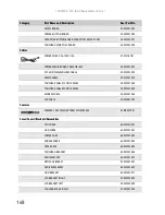
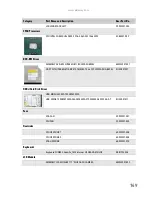
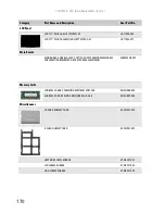
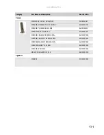
Страница 169: ...CHAPTER6 163 FRU Field Replaceable Unit list Introduction Exploded diagram FRU list ...

Страница 170: ...ever reasons a part number change is made it will not be noted on the printed Service Guide For ACER AUTHORIZED SERVICE PROVIDERS your Acer office may have a DIFFERENT part number code from those given in the FRU list of this printed Service Guide You MUST use the local FRU list provided by your regional Acer office to order FRU parts for repair and service of customer machines Important To scrap ...

Страница 171: ...Palm rest Battery Optical drive Hard drive Memory cover Cooling assembly Keyboard Keyboard cover Speakers Modemjack USB board Hard drive cover Hard drive Fan EMI Shield System board Fan Cooling assembly Power button board Media button board Notebook bottom ...

Страница 172: ... 6 FRU Field Replaceable Unit list 166 Notebook LCD panel Webcam LCD panel Left hinge bracket Inverter Right hinge bracket Left hinge Antenna Antenna Antenna Right hinge LCD panel lid LCD front panel LCD cable ...

Страница 173: ...ESS ANTENNA AUX BLACK 50 W2301 009 Batteries BATTERY PACK LI 9CELL 2 6AH SMP BT 00907 006 Reviewer This battery is not in the printout Boards Reviewer This board is not in the printout INVERTER BOARD 17 YEC YNV W10 19 TK901 004 WIRELESS LAN BOARD 512AN_MMWG SHIRLEY PEAK 5100 MM 895361 KI SPM01 003 MODEM BOARD LITEON CONEXANT UNIZION ZION RD02 D330 A55024Z18G 54 W2301 001 TOUCH PAD BUTTON BOARD 55 ...

Страница 174: ...301 004 TOUCHPAD CABLE 25PIN 140MM 50 W2301 005 MODEM CABLE 50 W2301 006 LCD CABLE 50 W2301 007 Cameras CAMERA 1 3M CHICONY CNF614121004960L 57 W2301 001 Cases Covers Brackets Assemblies CPU COVER 60 W2301 001 HDD COVER 60 W2301 002 LOWER CASE 60 W2301 003 MIDDLE COVER 60 W2301 004 UPPER CASE 60 W2301 005 TOUCHPAD BRACKET 60 W2301 006 VOLUME PLATE 40 W2301 001 OPTICAL BRACKET 33 W2301 001 DVD RW R...

Страница 175: ...L KU 00801 027 HDDs Hard Disk Drives HDD MODULE 200G 7200RPM SATA HDD 200GB 7200RPM SATA SEAGATE SATA ST9200420AS FW 3 AAA 7 KH 20001 011 Fans VGA FAN 23 W2301 001 CPU FAN 23 W2301 002 Heatsinks CPU HEATSINK 1 60 W2301 008 CPU HEATSINK 2 60 W2301 008 VGA HEATSINK 60 W2301 010 Keyboards Keyboard SUNREX Godzilla_IMV Internal US ORANGE COLOR KB INT0S 024 LCD Module ASSEMBLY LCD MODULE 17 1 WUXGA W CA...

Страница 176: ...ODEM MODEM CABLE CPU DIMM PM45 DISCRETE VRAM SAM512MB MB W050B 007 Memory Cards SODIMM 2G DDR3 SAMSUNG M471B5673DZ1 CF8 KN 2GB0B 005 SODIMM 2G DDR3 ELPIDA EBJ21UE8BAU0 AE E KN 2GB09 002 Miscellaneous SD CARD DUMMY CARD 42 W2301 002 E CARD DUMMY CARD 42 W2301 001 HEATSINK SCREW RUBBER 47 W2301 001 LCD SCREW RUBBER 47 W2301 002 ODD SCREW RUBBER 47 W2301 003 Category Part Name and Description Acer Pa...

Страница 177: ...30 SCREW M2 5 L8 NYLOK CR3 86 00E34 738 SCRW MAC WA M2L3 BZNYLOK CR3 86 W2301 002 SCRW MAC WAF M3 3 BZNYLOK CR3 86 W2301 003 SCRW DOR WAF M2 4 BZNYLOK CR3 86 W2301 004 SCRW NYLOK M2 5 L3 NI ROH 86 W2301 005 SCRW M2 5X3 NYLOK 86 W2301 006 M2 5L10 KUAOLENG THICK 1 3 86 W2301 007 Speakers SPEAKER 23 W2301 003 Category Part Name and Description Acer Part No ...

Страница 178: ...CHAPTER 6 FRU Field Replaceable Unit list 172 ...

Страница 179: ...APPENDIXA 173 Model definition and configuration Information not available at time of printing ...

Страница 180: ...APPENDIX A Model definition and configuration 174 Model RO Country Acer Part No Description CPU LCD SO DIMM 1 SO DIMM 2 HDD 1 GB ODD Wireless LAN Bluetooth VoIP Phone ...

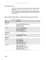
Страница 181: ...APPENDIXB 175 Test compatible components Introduction Microsoft Windows Vista Environment Test ...

Страница 182: ... Monitor ViewSonic Professional Series G220 21 Monitor Philips 109P 19 Monitor MAG 810FT II 19 Monitor LCD Monitor ViewSonic 19 LCD VA1912W Monitor ViewSonic 20 LCD VA2012W Monitor Samsung 22 LCD 225DW Monitor Philips 15 150B5 Monitor ASUS 22 LCD MW221u monitor EIZO 17 LCD FlexScan L586 monitor HDMI Port Test LCD TV BenQ VH3243 32 HDMI LCD TV Panasonic TC 37MPK 37 HDMI LCD TV BenQ VL3735 LCD TV US...

Страница 183: ...eless LAN Adapter Afast Ethernet Adapter USB2 0 D Link Wireless LAN adapter 802 11a b or b only D Link AirPlus DWL 120 2 4GHz Wireless USB Adapter USB Storage Zynet 2 5 External Enclosure SATA Usb2 0 Box Sony 2 5 ExtERNAL BOX Slim Kit USB 2 0 Mass Storage 2 5 HDD combo case IO DATA 250GB eSATA HDD SanDisk Cruzer USB Flash Drive Micro 1 0GB HP DL702 USB 128MB Digital Drive Transcend USB 512MB Flash...

Страница 184: ...s6 Transcend SD 512MB Transcend 150X Ultra Speed SD 4GB Transcend SD HC 4GB A DATA 150X Turbo SD 4GB A DATA miniSD 512MB KINGMAX mini SD Adapter 512MB Mini SD Toshiba SDHC 4GB Class4 SanDisk Micro SD 6GB TOSHIBA Micro SD 2GB MMC MMC Plus MMC Pro RS MMC RS MMC Mobile A DATA MultiMedia Card 256MB A DATA MultiMedia Card plus 1GB 200X A DATA RS MMC 256MB Transcend MMC Plus 4GB Transcend RS MMC 512MB R...

Страница 185: ...APPENDIXC 179 Online support information ...

Страница 186: ...oad information on all of Acer s Notebook Desktop and Server models including Service guides for all models User s manuals Training materials BIOS updates Software utilities Spare parts lists TABs Technical Announcement Bulletin For these purposes we have included an Acrobat File to facilitate the problem free downloading of our technical material Also contained on this website are Detailed inform...

Страница 187: ...icator 22 cards Express Card slot 17 memory card slot 17 CD controlling playback 24 32 chipset Bluetooth 11 modem 12 USB 12 wired Ethernet 11 wireless Ethernet 11 clicking 31 connections audio 17 broadband Internet 17 cable modem 17 dial up modem 18 digital camera 16 17 digital video camera 17 DSL modem 17 eSATA 18 Ethernet 17 external audio 17 external diskette drive 16 17 external speakers 17 Fi...

Страница 188: ...res 23 keys 23 locating 20 USB port 16 17 keyboard or auxiliary input device check 145 keys application 23 arrow 23 brightness 25 directional 23 Fn 23 function 23 Hybrid Sleep 24 LCD brightness 25 LCD CRT 24 navigation 23 numeric keypad 23 Sleep 24 system 23 system key combinations 23 toggle display 24 Windows 23 wireless Ethernet 24 L latch battery 19 LCD panel release 16 LCD panel release latch ...

Страница 189: ...d 22 Pad Lock 22 power 16 specification 13 toggle on or off 24 Suspend 24 switch wireless network 16 system block diagram 5 check procedures 144 system keys combinations 23 locating 23 T television HDMI out jack 17 top 162 touchpad buttons 30 check 147 clicking 31 double clicking 31 dragging screen objects 31 locating 20 moving pointer 30 31 moving screen objects 31 opening files folders and progr...

Страница 190: ...Index 184 ...

Страница 191: ......

Страница 192: ...MAN GODZILLA SVC GDE R1 07 08 ...

Отзывы: