190-00726-00 Rev. J
Garmin G900X Pilot’s Guide
107
ENGINE INDICATION SYSTEM
SY
STEM
O
VER
VIEW
FLIGHT
INSTRUMENTS
EIS
AUDIO P
ANEL
& CNS
FLIGHT
MANA
GEMENT
HAZARD
AV
OID
ANCE
AFCS
ADDITIONAL
FEA
TURES
APPENDICES
INDEX
1
9
8
3
2
7
10
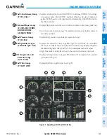
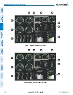
Figure 3-14 Engine Page (RV-9/9A with O-320-series)
5
4
6
ELECTRICAL
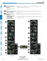
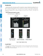
The Electrical Group uses vertical bar indicators to display currents for the alternator, battery, standby
alternator or battery (optional), and voltages for the main and essential buses for 14- or 28-V systems. The
ammeter scale(s) are dependent on the installed alternator (60-, 70-, 80-, 100-A).
The Auxiliary Ammeter scale is dependent upon the type of optional standby power installed: 0 to 70 A
(alternator) or -30 to 70 A (battery).
Figure 3-15 Electrical Group
Alternator Current
Essential Bus Voltage
Battery Current
Auxiliary Ammeter
(Optional Standby
Battery Shown)
Main Bus Voltage
Содержание G900X
Страница 1: ...G900X Integrated Flight Deck Pilot s Guide ...
Страница 2: ......
Страница 10: ...Garmin G900X Pilot s Guide 190 00726 00 Rev J vi WARNINGS CAUTIONS AND NOTES Blank Page ...
Страница 16: ...Garmin G900X Pilot s Guide 190 00726 00 Rev J xii TABLE OF CONTENTS Blank Page ...
Страница 707: ......


