Maintenance Manual
190-02472-02
G3X Touch EFIS Part 23 AML STC
Revision 2
Page 34
d. Verify that the CAN HI and CAN LO signals are not shorted to ground (this can happen
when shielded wire is installed incorrectly).
e. Measure the resistance between CAN HI and shield ground, and CAN LO and shield
ground. Verify resistance is several hundred kilohms (K
Ω
) or greater.
7. Verify that the CAN HI and CAN LO signals are not swapped or open-circuited at any LRU
connector.
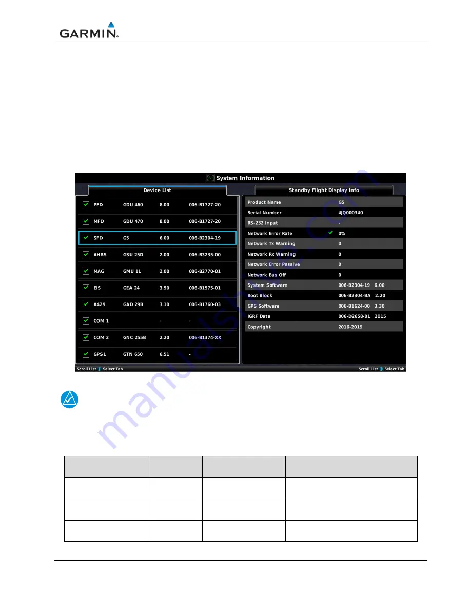
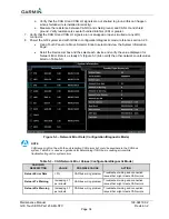
8. Power the G3X system and with GDUs in configuration/diagnostic mode, reference section 3.2.3.
Using Touch Panel or a Move Selector Knob to select and view the System Information
Page.
Scroll the Device List box and the select each device and verify the value displayed for
Network Error Rate is a steady 0% (Figure 5-3).Also verify the other network counts values
listed on Table 5-3.
Figure 5-3 – Network Error Rate (Configuration/Diagnostic Mode)
NOTE
CAN issue might not be with the unit reporting CAN errors but could be anywhere in the CAN bus
system. Table 5-3 is used as a guidance for determining if CAN bus is causing errors while
troubleshooting unit or system errors.
Table 5-3 – CAN Network Error Values (Configuration/Diagnostic Mode)
CAN INFO
DESCRIPTION
VALUE
POSSIBLE CAUSE
ACTION
Network Error Rate
> 0%
CAN bus wiring problem
Troubleshoot wiring and connection
issues that might create CAN errors
Network Tx Warning
Increasing
≥
1
per minute
CAN bus wiring problem
Troubleshoot wiring and connection
issues that might create CAN errors
Network Rx Warning
Increasing
≥
1
per minute
CAN bus wiring problem Troubleshoot wiring and connection
issues that might create CAN errors













![Navig[8]r NAVBIKE-GPS User Manual preview](http://thumbs.mh-extra.com/thumbs/navig-8-r/navbike-gps/navbike-gps_user-manual_3574097-01.webp)


