Maintenance Manual
190-02472-02
G3X Touch EFIS Part 23 AML STC
Revision 2
Page 62
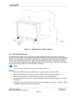
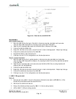
Figure 6-1 – GDU 460 Shown, (GDU 470 Similar)
6.1.1 PFD Configuration Module
The GDU 4X0 PFD display uses a configuration module designated as the master system configuration
module. The master system configuration module stores configuration data identical to the PFD configuration
data stored in the PFD memory. The PFD cross-checks the configuration module data against internal PFD
memory and self-configures to match the master system configuration module. The PFD also maintains
control of other LRUs’ configuration and calibration settings such as the GSU 25D. This allows critical data to
be retained with the airframe even if the PFD display is replaced.
NOTE
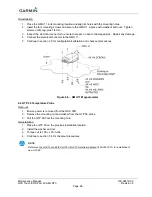
All item numbers (in parenthesis) in this procedure reference Figure 6-2
.
Removal:
1. Remove the PFD in accordance with Section 6.1 to gain access to connector J4X02.
2. Remove the backshell cover (8) from connector J4X02 by removing the two screws (7).
3. Remove the screw (4) securing the configuration module (1) to the backshell (6).
4. Lift the configuration module (1) out of the backshell (6) and disconnect the wiring harness (3) from
the module.
5. Inspect the wiring harness (3) and connector pins (2) for damage, loose wiring, or corrosion. Repair
any defects or replace components as necessary.


