Maintenance Manual
190-02472-02
G3X Touch EFIS Part 23 AML STC
Revision 2
Page 65
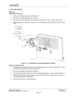
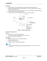
Figure 6-4 – Remote mounted GSU 25D
Reinstallation:
GDU-mounted GSU 25D:
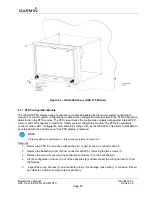
1. Place the GSU 25D on the back of the GDU in the same mounting orientation as it was when
removed. Align GSU holes with the mounting holes on the back of the GDU.
2. Insert the four mounting bolts and secure the GSU 25D on the back of the GDU.
3. Connect the pitot and static lines.
4. Inspect the electrical connector to ensure there are no bent or damaged pins. Repair any damage.
5. Connect
the
electrical
connectors to the GSU 25D.
6. Reinstall the GDU as noted in Section 6.1.
7. Continue to section 7.2 for configuration and checkout procedures.
Remote mounted GSU 25D:
1. Place the GSU 25D on the mounting location in the same mounting orientation as it was when
removed. Align GSU holes with the holes on the mounting location. Connect the electrical connectors
to the GSU 25D.
2. Insert the four mounting bolts or screws and secure the GSU 25D to the mounting location with
washers and nuts (as applicable).
3. Connect the pitot and static lines.
4. Inspect the electrical connector to ensure there are no bent or damaged pins. Repair any damage.
5. Connect
the
electrical
connectors to the GSU 25D.
6. Continue to section 7.2 for configuration and checkout procedures.
6.3
GMU 11 Magnetometer
Removal:
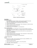
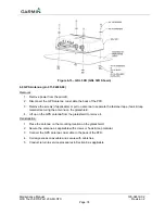
1. Gain access to the GMU 11. Refer to the location information recorded in APPENDIX A of this
document and maintained with the aircraft records.
2. Disconnect the electrical connector.
3. Remove the 4 fasteners that secure the GMU 11 to the mounting location.
4. Lift the GMU 11 off the mounting location.


