Maintenance Manual
190-02472-02
G3X Touch EFIS Part 23 AML STC
Revision 2
Page 47
5.9 Garmin GFC 500 Failure Messages
During operation of the GFC 500 AFCS, the G3X Touch GDU may annunciate a failure or fault that is
specific to the GFC 500 Autopilot system. Refer to the
GFC 500 Autopilot with Electronic Stability Protection
Part 23 AML STC Maintenance Manual with Instructions for Continued Airworthiness
(190-02291-01), for
assistance in troubleshooting the problem.
5.10 Loss of Non-Garmin Autopilot Heading and/or Course Datum
If a Non-Garmin autopilot loses the capability to couple and track Heading and/or Course Datum:
1. Complete troubleshooting as directed and applicable in Sections 5.1, 5.2 (CAN bus troubleshooting),
5.4.2 (for loss of heading datum) and 5.7 (for loss of course and GPSS datum).
2. Inspect and verify the ARINC 429 wiring between GPS navigator, GAD 29B and the autopilot
computer.
3. Inspect the analog wiring between the GAD29B and the autopilot computer.
4. Verify the G3X Touch and GPS navigator configurations have not changed. Reference APPENDIX B
5. Verify autopilot computer is functioning properly. Reference the autopilot manufacturer’s
troubleshooting procedures.
6. If problem persists, replace the GAD 29B with a known good unit.
5.11 Miscellaneous Alerts
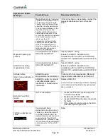
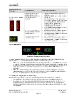
Table 5-12 – Miscellaneous Alerts
Alert Message
Possible Cause
Recommended Action
TAWS FAIL
Database error
Loss of GPS position
Verify databases are up to date
Verify GPS signal is available
Power removed from GAD 27
Defective or failed GAD 27
Ensure GAD 27 circuit breaker is not open.
Inspect wiring and electrical connections.
If problem persists, replace the GAD 27
with a known good unit.
GDU 470 display is in split
screen mode and CAUTION
annunciations are not
displayed.
Select full screen format to view
messages
Select
on the lower section of
the display
GDU 470 display is in split
screen mode and WARNING
annunciations are not
displayed.
5.12 Aircraft
Harness/LRU
Connectors
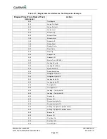
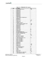
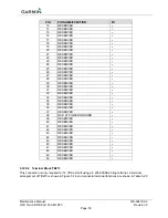
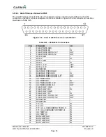
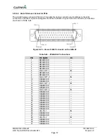
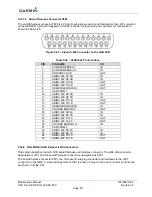
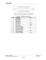
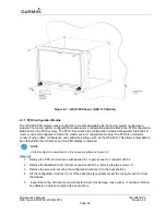
This section describes the aircraft harness connectors and associated LRU connectors. The pin
arrangement for each LRU connector is shown and the LRU connector arrangement for units with more than
one connector will be shown in the following sections. LRU connector arrangements will show the aircraft
harness connector designations. Reference the
G3X Touch EFIS Part 23 AML STC Installation Manual
(190-
02472-01) for further detail.

