Maintenance Manual
190-02472-02
G3X Touch EFIS Part 23 AML STC
Revision 2
Page 72
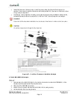
Install the transducer and fuel hoses routed as far away from the aircraft exhaust system as
practical. Securely wrap and the transducer with Aeroquip AE102-( ) fire-sleeve if within six inches
of any exhaust component.
Line fittings, routing, alignment, bonding, and support spacing must be installed as defined in the
aircraft maintenance manual or section 8-31 of AC 43.13-1B, “
Aircraft Inspection and Repair
”.
WARNING
Ensure the fuel flow transducer installation does not introduce thread sealant or debris into the fuel system.
CAUTION
Do not blow pressurized air through the flow transducer.
Figure 6-11 – Fuel Flow Transducer Installation Example
6.7 GAD 29B ARINC 429 Adapter
Removal:
1. Gain access to the GAD 29B. Refer to the location information recorded in APPENDIX A of this
document and maintained with the aircraft records.
2. Disconnect the GAD 29B connectors.
3. Remove the four screws that hold the GAD 29B to the mounting location.
4. Lift the GEA 24 off its mounting location.


