


G1000 Supplemental Maintenance Manual
Page 8-5
Textron Nav III Series
Revision 3
190-02128-04
Antenna Verification
The following test assures the antennas and coaxial cables are properly connected. The GTS
800 must be in Ground Test mode.
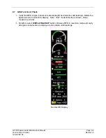
1. On the
Map
– Traffic Map
page of the MFD, press the
TAS OPER
softkey. A self-test
of the antenna circuit is initialized. If the MFD displays FAILURE at the upper left corner
of the traffic display area, it will be necessary to recheck the coaxial connections. If MFD
displays OPERATE without indicating a fault, proceed to the next step of antenna
verification.
2. Ensure that the transmitter or receiver (TX/RX) that you are testing is significantly closer
to the ramp tester than another operating RX/TX, or erroneous and inaccurate results
may occur. All four quadrants (0, 90, 180 and 270 degrees) will be similarly tested to
verify bearing of simulated intruder supplied via the ramp tester are correctly displayed on
the
Map
– Traffic Map
page of the MFD.
3. Set up a stationary intruder by selecting the following on the ramp tester:
•
Intruder type: ATCRBS.
•
Intruder Start Distance: 2 nm
•
Intruder Start Altitude: 600 feet above field elevation
•
Vertical Speed: 0 fpm
•
Velocity: 0 kts (on some ramp testers, a velocity greater than 0 kts is required and
a stationary intruder is created by not starting the scenario.)
4. Position ramp tester at 0 degrees.
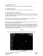
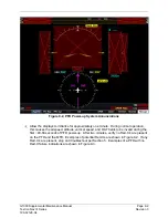
5. Initiate the intruder scenario and verify a target is annunciated on the
Map
– Traffic Map
page of the MFD at the correct bearing of approximately 0 degree azimuth at 2 NM and
co-altitude (read as +06 above a filled diamond indicating proximate traffic).
6. On the ramp tester, toggle intruder traffic to standby or off.
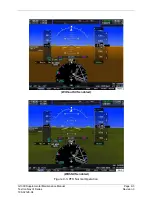
7. Reposition ramp tester and reengage the same intruder scenario for 90, 180 and 270
degrees.
8. Verify a target is annunciated on the
Map
– Traffic Map
page of the MFD at the same
bearing as the ramp tester.
9. If the bearing is not as anticipated or multiple targets are displayed during tests, verify the
following:
•
Coax cable connectors are properly secured at the GA58 antennas and GTS unit.
•
Connections are made to the proper channels and color-coded heat shrink is the
same color on both ends of coax cables
•
Connectors are correctly installed on coax cables
10. If no other service is to be performed, continue to the return-to-service checks in Section
Содержание G1000 NXi
Страница 61: ......