13–8–609 Page 17
FIGURE 4–3 – MINIMUM PRESSURE/CHECK VALVE
201EBE797
(Ref. Drawing)
See description under “Air Control Components,” be-
low, for construction and operation information.
INSTRUMENTS – All units incorporate the following
instruments and indicators:
Oil Sight Gauges (FIGURE 1–3, page 3) – These
gauges indicate the level of the oil in the reservoir. See
Section 5, page 26, “Lubrication, Oil Cooler, Oil Filter
and Separator”, for information on how to correctly read
these gauges. All other instruments are a part of the
Auto–Sentry S controller. See “Air Control Compo-
nents,” below.
AIR CONTROL COMPONENTS – All units incorpo-
rate the following air control components. See
FIGURE 4–1, page 15, for schematic tubing diagram.
Inlet Valve (FIGURE 4–2, page 16) – The inlet valve
is a pilot–actuated valve that restricts the inlet to control
capacity and closes to unload the compressor. At shut-
down the inlet valve closes to function as a check valve
and prevent backflow of air.
As control pressure is increased the valve will begin to
close, restricting the inlet and reducing compressor ca-
pacity. Approximately 18 psig (1.2 Bar) of control pres-
sure is required to close the inlet valve completely.
When closed, the inlet valve prevents the flow of air in
either direction. With optional modulating control fea-
ture: when the control pressure is less than 18 psig (1.2
Bar), the inlet valve will modulate to match compressor
capacity to system demand.
Blowdown Valve (FIGURE 4–2, page 16) – The blow-
down valve is a two–way solenoid valve that is piped
into the oil separator outlet, but ahead of the check
valve. When the solenoid is de–energized, the blow-
down valve opens, and the oil system is blown down.
When the solenoid is energized, the blowdown valve
closes, and allows the oil system to pressurize.
Minimum Pressure/Check Valve (FIGURE 4–3) –
An internal spring–loaded minimum pressure valve is
used in the final discharge line to provide a positive
pressure on the oil system even when the air service
valve is fully open. The valve senses upstream pres-
sure. If demand for air exceeds the compressor capac-
ity, the valve throttles the flow to maintain a minimum
pressure on the upstream (oil reservoir) side of the
valve. When pressure rises above the minimum pres-
sure (standard setting 60 to 65 PSIG, 4.1 to 4.5 Bar) the
valve reaches the full open position.
A check valve incorporated in the minimum pressure
valve prevents backflow of air from the shop air line
when the unit stops, unloads or is shut down.
The valve does not require maintenance or adjustment.
If the valve fails to function, it must be replaced be-
cause it is not field adjustable or field repairable.
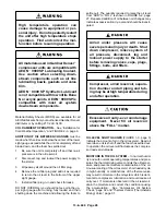
Air/oil under pressure will cause
severe personal injury or death. Shut
down compressor, relieve system of
all pressure, disconnect, tag and
lockout power supply to the starter
before removing valves, caps, plugs,
fittings, bolts, and filters.
STARTER/CONTROL BOX (FIGURE 1–3, page 3) –
The following control components are located on the
combination starter/control box.
Hourmeter – A continuous reading (nonreset) type
hourmeter displays the accumulated operating time of
the unit and provides a convenient means for schedul-
ing changes of oil and servicing of filters, separators
and other devices.
Auto–Sentry S Controller With Keypad – Monitors
and controls compressor operation.
Emergency Stop Pushbutton – Removes power
from the microprocessor controller outputs to provide
a positive means of stopping the unit in an emergency
situation.
CONTROL SYSTEM OPERATION – See
FIGURE 4–9, page 23. The following are operations of
the Auto–Sentry S Controller.
“STOP/RESET” Button With LED – This button is
used to stop the compressor under ordinary conditions.
It is also used to extinguish any fault LED’s that are illu-
minated. In addition, it is used in the procedure to adjust
operating pressure. See “Programming the Load–Un-
load Pressure Setpoints,” page 19. The LED is illumi-
nated whenever the unit is stopped for any reason EX-
CEPT a normal stop in one of the “AUTO” modes. A
flashing LED indicates that a reset is required.
Содержание ELECTRA-SCREW EBE DH-15 HP
Страница 10: ...13 8 609 Page 2 200EBE797 Ref Drawing FIGURE 1 2 PACKAGE MINIMUM PRESSURE CHECK VALVE SEPARATORS OIL FILTER...
Страница 11: ...13 8 609 Page 3 200EBE797 Ref Drawing FIGURE 1 3 PACKAGE OIL LEVEL GAUGES STARTER CONTROL BOX AIR FILTER...
Страница 14: ...13 8 609 Page 6 DECALS 206EAQ077 212EAQ077 218EAQ077 211EAQ077 207EAQ077...
Страница 15: ...13 8 609 Page 7 DECALS 216EAQ077 217EAQ077 222EAQ077 221EAQ077 208EAQ077...
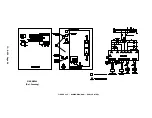
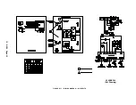
Страница 32: ...13 8 609 Page 24 FIGURE 4 10 WIRING DIAGRAM DUAL CONTROL 218EBE546 Ref Drawing...
Страница 33: ...13 8 609 Page 25 FIGURE 4 11 WIRING DIAGRAM WYE DELTA 220EBE546 Ref Drawing...
Страница 51: ......


