13–8–609 Page 15
SECTION 4
CONTROLS & INSTRUMENTATION
GENERAL – The Gardner Denver
Electra–Screw
compressor is supplied with a factory mounted starter
and complete controls as standard equipment. The
standard control system consists of constant run load/
unload operation, or auto start/timed stop operation.
Lead/Lag operation of two EBE compressors is also
possible without additional equipment. Inlet valve
modulation is standard.
PROTECTIVE DEVICES – All compressors incorpo-
rate the following protective devices:
Standard Domestic Motor Protection Devices –
Overload heaters are furnished for the starter in the
voltage range specified. There are three (3) overloads
in the starter of proper size for the starter and its enclo-
sure. An overload trip is indicated by the “MOTOR
OVERLOAD” LED located on the control keypad.
Optional Domestic Motor and Standard Interna-
tional Protective Devices – Wye–Delta Starter –
Overload heaters are furnished for the starter in the
voltage range specified. There are three (3) overloads
in the starter of proper size for the starter and its enclo-
sure. Note that motor nameplate current must be multi-
plied by .577 for wye–delta starters. Proper starter coil
and contact action is also monitored to ensure proper
operation.
Separator Differential Pressure – The Separator dif-
ferential pressure is continually monitored by the mi-
croprocessor controller. At a differential of approxi-
mately 8 PSI (.6 Bar), the “CHANGE SEPARATOR”
LED located on the control keypad flashes indicating
required maintenance. If the warning is ignored, and
the separator differential continues to increase, the mi-
croprocessor controller will stop the unit at 15 PSI (1
Bar) and the LED will remain on steady. See “Control
System Operation,” page 17, for further information on
operation of the microprocessor controller.
High Discharge Temperature – The compressor is
protected from high discharge temperature by two in-
dependent thermistor probes. One probe is located in
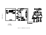
FIGURE 4–1 – CONTROL SCHEMATIC
202EBE797
(Ref. Drawing)
Содержание ELECTRA-SCREW EBE DH-15 HP
Страница 10: ...13 8 609 Page 2 200EBE797 Ref Drawing FIGURE 1 2 PACKAGE MINIMUM PRESSURE CHECK VALVE SEPARATORS OIL FILTER...
Страница 11: ...13 8 609 Page 3 200EBE797 Ref Drawing FIGURE 1 3 PACKAGE OIL LEVEL GAUGES STARTER CONTROL BOX AIR FILTER...
Страница 14: ...13 8 609 Page 6 DECALS 206EAQ077 212EAQ077 218EAQ077 211EAQ077 207EAQ077...
Страница 15: ...13 8 609 Page 7 DECALS 216EAQ077 217EAQ077 222EAQ077 221EAQ077 208EAQ077...
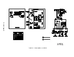
Страница 32: ...13 8 609 Page 24 FIGURE 4 10 WIRING DIAGRAM DUAL CONTROL 218EBE546 Ref Drawing...
Страница 33: ...13 8 609 Page 25 FIGURE 4 11 WIRING DIAGRAM WYE DELTA 220EBE546 Ref Drawing...
Страница 51: ......


