13–8–609 Page 30
1.
Be sure the unit is completely off and that no air
pressure is in the oil reservoir.
2.
Disconnect, tag and lockout the power supply to
the starter.
3.
Wipe away all dirt around the oil filler plug.
4.
Remove the oil filler plug and add oil as required
to return the oil level to the bottom of the upper
sight gauge.
5.
Install the oil filler plug and operate the unit for
about a minute allowing oil to fill all areas of the
system. Check for leaks.
6.
Shut down unit, allowing the oil to settle, and be
certain all pressure is relieved.
7.
Add oil, if necessary, to bring level to “FULL.”
On unloaded operation and after shutdown some oil will
drain back into the oil reservoir and the oil level will read
over “FULL”. DO NOT DRAIN OIL TO CORRECT. On
the next start, oil will again fill the system and the gauge
will indicate operating at the proper level. DO NOT
OVERFILL (you should not see oil in the upper sight
gauge when running fully loaded) as oil carryover will
result. The quantity of oil required to raise the oil level
from “ADD” to “FULL” is shown in FIGURE 5–2, page
27, this section. Repeated addition of oil between oil
changes may indicate excessive oil carryover and
should be investigated.
Use only CLEAN containers and funnels so no dirt en-
ters the reservoir. Provide for clean storage of oils.
Changing the oil will be of little benefit if done in a care-
less manner.
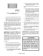
Excessive oil carry–over can damage
equipment. Never fill oil reservoir
above the “FULL” marker.
COMPRESSOR OIL FILTER (FIGURE 1–2, page 2)
– This replaceable element filter is a vital part in main-
taining a trouble–free compressor, since it removes dirt
and abrasives from the circulated oil. The filter is
equipped with a relief valve that opens in the event the
element becomes dirty enough to block the flow of oil.
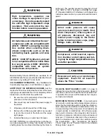
Improper oil filter maintenance will
cause damage to equipment. Replace
filter element every 1000 hours of op-
eration. More frequent replacement
could be required depending on oper-
ating conditions. A filter element left
in service too long may damage
equipment.
Use only the replacement element shown on the filter
tag or refer to the parts list for the part number. Use the
following procedure to replace the filter element. Do
not disturb the piping.
Air/oil under pressure will cause
severe personal injury or death. Shut
down compressor, relieve system of
all pressure, disconnect, tag and
lockout power supply to the starter
before removing valves, caps, plugs,
fittings, bolts, and filters.
Compressor, air/oil reservoir, separa-
tion chamber and all piping and tub-
ing may be at high temperature during
and after operation.
1.
Stop the unit and be sure no air pressure is in the
oil reservoir.
2.
Remove the spin–on element.
3.
Clean the gasket face of the filter body.
4.
Coat the new element gasket with clean lubricant
used in the unit.
5.
Screw the new element on the filter body and tight-
en by hand. Tighten 1/2 turn more after gasket
makes contact. DO NOT OVERTIGHTEN ELE-
MENT.
6.
Run the unit and check for leaks.
Содержание ELECTRA-SCREW EBE DH-15 HP
Страница 10: ...13 8 609 Page 2 200EBE797 Ref Drawing FIGURE 1 2 PACKAGE MINIMUM PRESSURE CHECK VALVE SEPARATORS OIL FILTER...
Страница 11: ...13 8 609 Page 3 200EBE797 Ref Drawing FIGURE 1 3 PACKAGE OIL LEVEL GAUGES STARTER CONTROL BOX AIR FILTER...
Страница 14: ...13 8 609 Page 6 DECALS 206EAQ077 212EAQ077 218EAQ077 211EAQ077 207EAQ077...
Страница 15: ...13 8 609 Page 7 DECALS 216EAQ077 217EAQ077 222EAQ077 221EAQ077 208EAQ077...
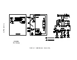
Страница 32: ...13 8 609 Page 24 FIGURE 4 10 WIRING DIAGRAM DUAL CONTROL 218EBE546 Ref Drawing...
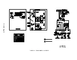
Страница 33: ...13 8 609 Page 25 FIGURE 4 11 WIRING DIAGRAM WYE DELTA 220EBE546 Ref Drawing...
Страница 51: ......


