


13–8–609 Page v
INDEX
Grease Recommendations, Electric Motor
12
. . . . . . .
Grounding
11
. . . . . . . . . . . . . . . . . . . . . . . . . . . . . . . . . . .
High Air Temperature LED
18
. . . . . . . . . . . . . . . . . . . . .
High Discharge Temperature
15
. . . . . . . . . . . . . . . . . . .
High Temperature Operation
27
. . . . . . . . . . . . . . . . . . .
Hourmeter
17
. . . . . . . . . . . . . . . . . . . . . . . . . . . . . . . . . . .
Inlet Line
11
. . . . . . . . . . . . . . . . . . . . . . . . . . . . . . . . . . . .
Inlet Line Lengths
11
. . . . . . . . . . . . . . . . . . . . . . . . . . . .
Inlet Tube
34
. . . . . . . . . . . . . . . . . . . . . . . . . . . . . . . . . . .
Inlet Valve
17
. . . . . . . . . . . . . . . . . . . . . . . . . . . . . . . . . . .
INSTALLATION, SECTION 2
8
. . . . . . . . . . . . . . . . . . .
Installation, General
8
. . . . . . . . . . . . . . . . . . . . . . . . . . .
Installation for Cold Weather Operation
10
. . . . . . . . .
Instructions for Ordering Repair Parts
iii
. . . . . . . . . . . .
Instruments
17
. . . . . . . . . . . . . . . . . . . . . . . . . . . . . . . . . .
Lead–Lag Operation of Two Compressors
21
. . . . . . .
Lifting Unit
8
. . . . . . . . . . . . . . . . . . . . . . . . . . . . . . . . . . . .
Line, Discharge Service
11
. . . . . . . . . . . . . . . . . . . . . . .
Line, Inlet
11
. . . . . . . . . . . . . . . . . . . . . . . . . . . . . . . . . . .
Load–Unload Pressure Setpoints, Programming
19
.
Location
8
. . . . . . . . . . . . . . . . . . . . . . . . . . . . . . . . . . . . .
Lubricant, Recommended
26
. . . . . . . . . . . . . . . . . . . . .
Lubricant Change Procedure
27
. . . . . . . . . . . . . . . . . .
Lubrication, Motor
11
. . . . . . . . . . . . . . . . . . . . . . . . . . . .
Lubrication, Cooling and Sealing
1
. . . . . . . . . . . . . . . .
LUBRICATION, OIL COOLER, OIL FILTER &
SEPARATOR, SECTION 5
26
. . . . . . . . . . . . . . . . .
MAINTENANCE SCHEDULE, SECTION 8
36
. . . . . .
Minimum Pressure/Check Valve
17
. . . . . . . . . . . . . . . .
Moisture in the Oil System
28
. . . . . . . . . . . . . . . . . . . . .
Moisture Separator/Trap
10
. . . . . . . . . . . . . . . . . . . . . .
Motor Grease Recommendations
12
. . . . . . . . . . . . . .
Motor Lubrication
11
. . . . . . . . . . . . . . . . . . . . . . . . . . . . .
Motor Overload LED
18
. . . . . . . . . . . . . . . . . . . . . . . . . .
Motor Protection Devices
15
. . . . . . . . . . . . . . . . . . . . . .
Motor Regreasing Interval
12
. . . . . . . . . . . . . . . . . . . . .
Oil Change Interval
29
. . . . . . . . . . . . . . . . . . . . . . . . . . .
Oil Cooler, Compressor
31
. . . . . . . . . . . . . . . . . . . . . . .
Oil Filter, Compressor
30
. . . . . . . . . . . . . . . . . . . . . . . . .
Oil Reservoir
30
. . . . . . . . . . . . . . . . . . . . . . . . . . . . . . . .
Oil Reservoir Drain
9
. . . . . . . . . . . . . . . . . . . . . . . . . . . .
Oil Separator
Compressor
31
. . . . . . . . . . . . . . . . . . . . . . . . . . . . .
Inspection
32
. . . . . . . . . . . . . . . . . . . . . . . . . . . . . . .
Removal for Inspection or Replacement
32
. . . . .
Oil Sight Gauges
17, 28
. . . . . . . . . . . . . . . . . . . . . . . . .
Oil Specifications
26
. . . . . . . . . . . . . . . . . . . . . . . . . . . . .
Oil System
Compressor
26
. . . . . . . . . . . . . . . . . . . . . . . . . . . . .
Draining and Cleaning
29
. . . . . . . . . . . . . . . . . . . . .
Oil System Check
32
. . . . . . . . . . . . . . . . . . . . . . . . . . . .
Air and Oil Discharge Temperature
32
. . . . . . . . . .
Compressor Oil Inlet Temperature
32
. . . . . . . . . .
Oil Cooler Oil Pressure Differential
32
. . . . . . . . . .
Oil Cooler Temperature Differential
32
. . . . . . . . . .
Oil Inlet Pressure
32
. . . . . . . . . . . . . . . . . . . . . . . . .
Operation
Cold Ambient
28
. . . . . . . . . . . . . . . . . . . . . . . . . . . .
Control System
17
. . . . . . . . . . . . . . . . . . . . . . . . . . .
High Temperature
27
. . . . . . . . . . . . . . . . . . . . . . . .
Lead–Lag, of Two Compressors
21
. . . . . . . . . . . .
Piping, Control
11
. . . . . . . . . . . . . . . . . . . . . . . . . . . . . . .
Pressure and Temperature Digital Readouts
19
. . . . .
Pressure Differential Gauging
31
. . . . . . . . . . . . . . . . . .
Prestart–Up Instructions
13
. . . . . . . . . . . . . . . . . . . . . . .
Air Filter
13
. . . . . . . . . . . . . . . . . . . . . . . . . . . . . . . . .
Electrical
13
. . . . . . . . . . . . . . . . . . . . . . . . . . . . . . . .
Enclosure
14
. . . . . . . . . . . . . . . . . . . . . . . . . . . . . . .
Grounding
13
. . . . . . . . . . . . . . . . . . . . . . . . . . . . . . .
Operating Mode
14
. . . . . . . . . . . . . . . . . . . . . . . . . .
Piping
13
. . . . . . . . . . . . . . . . . . . . . . . . . . . . . . . . . . .
Содержание ELECTRA-SCREW EBE DH-15 HP
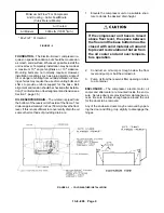
Страница 10: ...13 8 609 Page 2 200EBE797 Ref Drawing FIGURE 1 2 PACKAGE MINIMUM PRESSURE CHECK VALVE SEPARATORS OIL FILTER...
Страница 11: ...13 8 609 Page 3 200EBE797 Ref Drawing FIGURE 1 3 PACKAGE OIL LEVEL GAUGES STARTER CONTROL BOX AIR FILTER...
Страница 14: ...13 8 609 Page 6 DECALS 206EAQ077 212EAQ077 218EAQ077 211EAQ077 207EAQ077...
Страница 15: ...13 8 609 Page 7 DECALS 216EAQ077 217EAQ077 222EAQ077 221EAQ077 208EAQ077...
Страница 32: ...13 8 609 Page 24 FIGURE 4 10 WIRING DIAGRAM DUAL CONTROL 218EBE546 Ref Drawing...
Страница 33: ...13 8 609 Page 25 FIGURE 4 11 WIRING DIAGRAM WYE DELTA 220EBE546 Ref Drawing...
Страница 51: ......


