manualshive.com logo in svg
background image

3

Minimum pipe size (IPS)*

Dryers with One Stage Regeneration

Dryers with Two Stage Regeneration

(Standard)

(Optional)

Up to 50 feet of

Up to 100 feet of

Up to 50 feet of

Up to 100 feet of

pipe plus 4 fittings

pipe plus 4 fittings

pipe plus 4 fittings

pipe plus 4 fittings

525

3

4

4

4

775

4

4

4

6

1050

4

6

6

6

1300

6

6

6

6

1575

6

6

6

6

1825

6

6

6

8

2100

6

6

6

8

2625

6

8

8

8

3150

8

8

8

8

3675

8

8

8

10

4200

8

8

10

10

4725

8

10

10

10

5250

10

10

10

10

5800

10

10

10

10

*Exhaust piping configuration - For Models and configurations other than those listed above, contact the factory for assistance.

Dryer

Model

Number

* Use if high liquid loads are present and to protect the oil removal
   filter from gross contamination
** Install downstream where air has cooled to at least 150

°

F (66

°

C).

Figure 3.2 - Pipe Sizing Chart for Purge Exhaust Lines
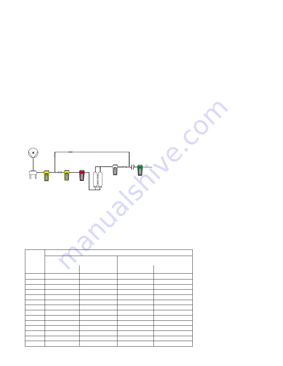
By-Pass Valves

Compressor

Aftercooler

Blower Purge

Dryer

Separator

High 

Efficiency

Oil Removal

Filter

Prefilter 

(Optional)*

Oil Vapor 

Removal Filter

(Optional)**

High Temperature 

Afterfilter

Figure 3.1

3.0  Installation

3.1  Location in Compressed Air System

The dryer should be located downstream of an
aftercooler and separator for best performance.

Prefilters are necessary to protect the desiccant beds
from liquid and solid contamination.  Locate the
prefilters as close to the dryer inlet as possible.  Use
an Air Line Filter in systems supplied by a non-
lubricated (oil free) air compressor.  In systems
supplied by a lubricated air compressor, use a High
Efficiency Oil Removal Filter.  A coarser filter will be
required upstream of the Oil Removal Filters if heavy
liquid or solid loads are present.

An afterfilter should be used to protect downstream
equipment from desiccant dust.  A High Temperature
Afterfilter, typically rated at a 450

°

F (232

°

C) operating

temperature and capable of removing all desiccant
fines 1 micron and larger should be provided.

The use of bypass valves and piping allows servicing
of the filters and/or dryer without interrupting the air
flow.

3.2  Ambient Temperature Limitations

The dryer should not be installed in an area where the
ambient temperature will exceed 120

°

F (49

°

C) or fall

below 40

°

F (4.4

°

C) unless the unit has been equipped

for operation in higher and/or lower ambient condi-
tions.

3.3  Mounting

Locate the dryer on a solid level floor.  Ensure the
dryer is level by grouting or shimming as necessary.
Securely anchor the dryer frame to the floor.  Provide
a four (4) foot (1.2 m) wide access area on all sides of
the dryer and overhead clearance of four (4) feet (1.2
m) for ease of servicing and visibility of instrumenta-
tion.

3.4  Air Inlet and Outlet Connections

Connect compressed air lines to the dryer inlet and
outlet using pipe of diameter equal to or larger than
the pipe size on the dryer.  Be sure to use a flange
gasket suitable for high temperature on the air outlet
flange.  The gasket must be able to withstand the
temperature spike that occurs at tower switchover
typically 300-325

°

F (149-163

°

C).

3.5  Electrical Hook-up

WARNING:

  These procedures require gaining access

to the dryer’s electrical enclosure(s).  All electrical
work must be performed by a qualified electrical
technician.

Connect the proper power supply to the dryer
according to the electrical drawings.  Be sure to
follow all applicable electrical codes.  After power is
connected to the dryer, manually engage the blower
motor starter to ensure proper blower rotation.

Dry contacts (voltage free) are provided in the main
electrical enclosure for a remote alarm.  The contact
ratings are shown on the electrical drawing.

3.6  Purge Exhaust Piping

In some installations, it may be necessary to pipe the
purge exhaust outdoors since condensation may
become a problem.  The purge exhaust piping must
be sized according to the chart shown in Figure 3.2.

Содержание DEB Series

Страница 1: ...vicing B Electrical This equipment requires electricity to operate Install equipment in compliance with national and local electrical codes Equipment supplied as standard is not intended for installat...

Страница 2: ...alternated on and off line so that dry desiccant is always in contact with the wet com pressed air resulting in a continuous supply of dry air downstream The switching from one tower to the other is...

Страница 3: ...perature and capable of removing all desiccant fines 1 micron and larger should be provided The use of bypass valves and piping allows servicing of the filters and or dryer without interrupting the ai...

Страница 4: ...Valve Purge Exhaust Left Purge Valve Left Purge Pilot Valve Left Inlet Valve Left Inlet Pilot Valve Purge Exhaust Muffler Right Depressurization Valve Temperature Gauge Back Front Air Inlet Left Depr...

Страница 5: ...s returned to normal operation auto stop disabled the dryer will return to demand cycle operation Auto stop is enabled or disabled through the opera tor interface The dryer can be returned to normal o...

Страница 6: ...the right tower and exits through the right purge valve V4 The blower intake air is filtered F1 to keep dust and dirt from entering the dryer The blower B1 and heater H1 are de energized when the temp...

Страница 7: ...The pressure in the right tower begins to rise and check valve V10 is seated Next the repressurization valve V15 is closed and the depressurization valve V6 is opened depressurizing the tower Finally...

Страница 8: ...all times 4 The F4 key performs three different functions as described in Menu s 3 4 and 5 The F4 key is only active when one of these menus is displayed 5 Use the UP ARROW and DOWN ARROW triangular...

Страница 9: ...4 to identify the active alarm s Then refer to the Troubleshooting Guide Section 5 0 for help in correcting the alarm condition After correcting an alarm condition use the F1 key on the operator inte...

Страница 10: ...ized Q1 0 9SOL Repressurization pilot valve When the solenoid is energized pilot air opens the repressurization valve when de energized pilot air closes the repressurization valve Q1 1 M Blower motor...

Страница 11: ...3 PLC Inputs Left Tower Drying and Outputs Step Number I O No Device L00 L01 L02 L03 L04 L05 L06 L07 L08 L09 L10 L11 L12 L13 L14 L15 I0 0 LPS I0 1 RPS I0 2 BPS I0 3 HHC I0 4 LTS I0 5 RTS I0 6 DPM I0 7...

Страница 12: ...r I O No Device L00 L01 L02 L03 L04 L05 L06 L07 L08 L09 L10 L11 L12 L13 L14 L15 I0 0 LPS I0 1 RPS I0 2 BPS I0 3 HHC I0 4 LTS I0 5 RTS I0 6 DPM I0 7 Jumper 1 I1 0 Jumper 2 I1 1 I1 5 Not Used Q0 0 1 SOL...

Страница 13: ...valve to on line tower L01 R01 0 5 0 5 Close inlet valve to off line tower L02 R02 4 0 4 0 Depressurize off line tower L03 R03 0 5 0 5 Examine off line tower pressure switch L04 R04 0 5 0 5 Open purg...

Страница 14: ...exhaust piping indicating valve is not completely closed Check for loss of pilot air see Section 5 1 4 Check for left purge pilot valve V13 failure check valve operation Repair or replace as necessar...

Страница 15: ...eration cycle 1 False alarm Heater hi limit thermocouple check thermocouple circuit for continuity Repair or replace as necessary Heater hi limit controller TC2 or TC4 malfunction check controller ope...

Страница 16: ...upply Check compressor supplying dryer 2 Excessive air demand Check equipment downstream of dryer 3 Faulty right tower pressure Check pressure switch operation using right tower pressure gauge switch...

Страница 17: ...clean or replace 2 Improper setting on blower pressure Check pressure switch operation Readjust switch setting or replace switch PS3 switch if defective 3 Loss of pressure to blower pressure Check lin...

Страница 18: ...ee Section 5 9 3 2 Right purge valve V4 failed to close See Section 5 9 5 3 Right depressurization valve V6 See Section 5 9 6 failed to close 4 Repressurization valve V15 failed Loss of pilot air see...

Страница 19: ...motor instruction tag 6 3 Blower Pressure Switch The blower pressure switch located in the main electrical enclosure is adjustable Verify that the switch is open when the blower is off and closed whe...

Страница 20: ...ages liability of the manufacturer is the original purchase price of the product or part THE FOREGOING WARRANTY IS EXCLUSIVE AND IN LIEU OF ALL OTHER WARRANTIES WHETHER WRITTEN ORAL OR STATU TORY AND...

Отзывы: