PP610/612 LED lighting controllers - User Manual
d
output current 4
e
maximum current rating of LEDs
p
pulse width (in milliseconds)
del
delay before pulse (in milliseconds)
The third line is for factory use.
The fourth and fifth lines are the de-bounce period for each input:
TiDd
Where:
i
input channel (1 or 2)
d
debounce period (in milliseconds)
For example, with:
Output channel 1
set up for four currents of 0.25mA, 25.7mA, 0.5A,
and 1.5A selected using combinations of inputs 1 and 2 and,
Output channel 2
set up to pulse a current of 5.35A for 100ms,
using input 1 as a trigger and a delay of 15ms, with a de-bounce
period of 20ms,
The result of the
ST
command will be:
01 M 06 E 1000 V 0.2, 25.7, 500, 1500,
02 M 01 E 7000 V 5350.0 D 15.0 P 0.10
P1 M 00 U
T01 D 20.00
T02 D 0.00
Clear error display from LEDs
GR
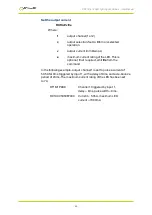
This command can return any of the five responses listed below:
>
No overcurrent operation.
EC1
Channel 1 has been overcurrent since the last
GR
command.
EC2
Channel 2 has been overcurrent since the last
GR
command.
ET
The PP610/PP612 has overheated and
switched off.
EC1EC2
Both channels have been overcurrent since the
last
GR
command.
—
40
—

