PP610/612 LED lighting controllers - User Manual
9
Operation
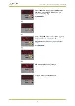
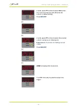
The PP610 can be set up using the push buttons and display on the front
of the unit. The setup is non-volatile, so the PP610 will resume the same
operation after a power cycle.
9.1
Startup
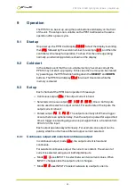
On power up, the PP610 will display
8
.
8
.
8
.
8
.
to test the display is working,
then
PP6
, followed by the version number, for example
017
, and then the
controller will be ready for operation. To show that the unit is operating
normally, an alternating pattern is shown on the display.
9.2
Cold start
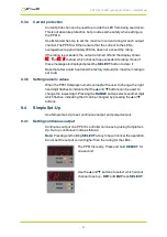
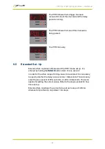
In the unlikely event that the non-volatile memory becomes corrupt the
PP610 may not start up properly. In this case the memory can be cleared
by powering up the PP610 while holding down the
SELECT
and
DOWN
buttons. The PP610 will display
COLD
for about 10 seconds while the
memory is cleared.
9.3
Set up
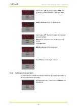
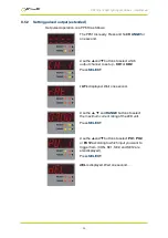
Each channel of the PP610 can operate in three ways:
Continuous output (
CON
): The output current is fixed.
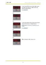
Selected continuous output (
SE 1
,
SE 2
,
SE12
): One or both inputs
can be used to select an output current. For each state of the inputs, the
output current is fixed.
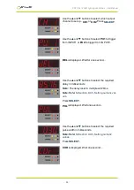
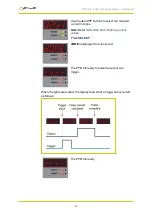
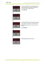
Pulsed output (
PU 1
,
PU 2
): The output is normally off. When a trigger
occurs, there is an optional delay, then the output is pulsed for a specified
time. A trigger is a leading edge on an input signal; that is, a transition from
0V to 5V on the input.
Each output operates asynchronously. For example, one output can be
pulsing while the other has a different output current selected.
9.3.1
Continuous output and selected continuous output
In continuous output mode (
CON
), the output current is fixed and
continuous.
For selected continuous output, the current is constant. The amount of
current is selected using one or both digital inputs.
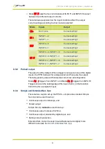
Mode
SE 1
uses INPUT1 to select between two current values. When
INPUT1 changes state the output current changes.
Mode
SE 2
uses INPUT2 to select between two output currents.
—
25
—

