Flex 620
Installation - Revision 5, 11/22/01
___________________________________________________________________________________________
27
Cabinet Mounting and Assembly Procedure
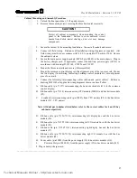
1. Unlock the front panel door. Lift up and remove.
2. Remove the mounting screws securing the three horizontal cross rails.
CAUTION !
Protect all cabinet components when mounting the control
panel to the foundation. Failure to cover enclosed circuit
boards from debris (metal shavings, dust etc.) may damage
components.
3. Secure the cabinet to the mounting foundation. Connect all conduit and secure.
4. Connect all field wiring. Reference all installation wiring diagrams as required. (All
field wiring must be in accordance with N.F.P.A. pamphlet #70 article #760.) Ensure
the cabinet is clean.
5. Secure the main power supply module (MPS-8 p/n 30889) to the main chassis. Plug in
the battery charger card. If applicable, connect the auxiliary power supply (APS-8) in
accordance with drawings D-W1142, C-W856 and C-W857.
6. Mount the three cross rails and secure (if disassembled).
7. Mount the common control display into the alignment pins of the top cross rail. Mount
the two display (for initiating, indicating, building control module etc.) into alignment
pins of cross rails.
8. Connect the following interconnecting cables (ribbon and power cables). Reference
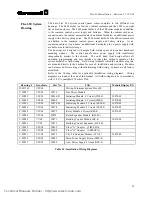
drawing D-W1142 all applicable wiring diagrams shown in above Table 1.
A. Ribbon cable (p/n 71157) interconnecting the bus driver module (J11) to the common
control display.
B. Ribbon cable (p/n 71158) interconnecting CPU module (ISBX1) and bus driver module
(P1).
C. 4 conductor interconnecting cable (p/n 30881) from CPU module (P3) to the bus driver
module (J13 - CPU power).
Note: All dual part numbers listed below refer to the correct cables for 4 and 8 bay
cabinets respectively
D. Ribbon cable (p/n 71156/71161) interconnecting left display bus and the bus driver
module (J6).
E. Ribbon cable (p/n 71155/71160) interconnecting left I/O module bus with the bus driver
module (J5).
F. Ribbon cable (p/n 71156/71161) interconnecting right display bus and the bus driver
module (J7).
G. Ribbon cable (p/n 77154/71159) interconnecting right I/O module bus with the bus
driver module (J8).
H. Power cable (p/n 30883) from the power supply (J3) to bus driver module (J16).
I.
Power cable (p/n 30882-01) from the power supply (J2) to bus driver module (J12).
9. Plug in battery charger card.
___________________________________________________________________________________________
Technical Manuals Online! - http://www.tech-man.com
Содержание FLEXALARM 620
Страница 2: ...This page intentionally blank Technical Manuals Online http www tech man com...
Страница 4: ...This page intentionally blank Technical Manuals Online http www tech man com...
Страница 6: ...This page intentionally blank Technical Manuals Online http www tech man com...
Страница 7: ...Technical Manuals Online http www tech man com...
Страница 8: ...This page intentionally blank Technical Manuals Online http www tech man com...
Страница 12: ...Technical Manuals Online http www tech man com...
Страница 13: ...This page intentionally blank Technical Manuals Online http www tech man com...
Страница 20: ...Technical Manuals Online http www tech man com...
Страница 21: ...Section 2 FLEXALARM 620 System Operation Technical Manuals Online http www tech man com...
Страница 34: ...Technical Manuals Online http www tech man com...
Страница 35: ...This page intentionally blank Technical Manuals Online http www tech man com...
Страница 64: ...Technical Manuals Online http www tech man com...
Страница 65: ...Section 4 FlexAlarm 620 Programming Technical Manuals Online http www tech man com...

