


The amplifier enable signal is defaulted to 5V, high amp enable. (the amplifier enable signal will be high
when the controller expects the amplifier to be enabled). It is recommended that if an amplifier requires a
different configuration, the controller should be be ordered with the desired configuration.
Pin-outs for the amplifier enable signal is found under the ICM being used:
A1. ICM-2900 Interconnect Module
ICM-1900 :
A3. ICM-1900 Interconnect Module
For full electrical specifications and wiring diagrams refer to:
External Amplifier Interface, pg 33
Once the amplifier enable signal is correctly wired , issuing a MO will disable the amplifier and an SH will
enable it.
Step C.
Connect the Encoders
(optional for stepper systems)
See Step 7. Connecting Encoder Feedback, pg 13.
Step D.
Connect the Command Signals
The DMC-42x0 has two ways of controlling amplifiers:
1. Using a motor command line (±10V analog output)
The motor and the amplifier may be configured in torque or velocity mode. In the torque mode, the
amplifier gain should be such that a 10V signal generates the maximum required current. In the
velocity mode, a command signal of 10V should run the motor at the maximum required speed.
2. Using step (0-5V, PWM) and direction (0-5V toggling line), this is referred to as Step/Dir for short.
Pin-outs for the command signals are found under the ICM being used:
The full list of ICM pin-outs are provided in
Step B
, above.
For full electrical specifications refer to:
External Amplifier Interface, pg 33
To configure the command signal type and other configuration commands see Table 2.10 below for a brief
synopsis. For a full list of configuration commands see the Command Reference.
Step E.
Issue the appropriate configuration Commands
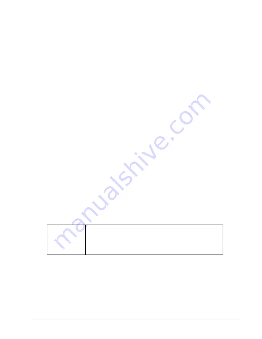
Command
Description
MT
The motor type command configures what type of control method to use
(switches axis between motor command or step/dir options)
TL
Servo only
. Limits the motor command line's continuous output in Volts
TK
Servo only
. Limits the motor command line's peak output in Volts
Table 2.10: Brief listing of most commonly used configuration commands for the motor command and step/dir lines
Step F.
If using a servo motor, continue to Step 11. Tune the Servo System, pg 23. If using a stepper motor, skip
to
Step G.
Step G.
Enable and use your motor
A SH will enable the external amplifier, once enabled, you can send DMC motion commands to move the
motor, see Chapter 6 Programming Motion, pg 55 for details.
Chapter 2 Getting Started ▫ 22
DMC-42x0 User Manual
Содержание DMC-42 0 Series
Страница 85: ...Chapter 6 Programming Motion 81 DMC 42x0 User Manual Figure 6 14 ECAM cycle with Z axis as master...
Страница 195: ...ICM 2900 PCB Layout Appendices 191 DMC 42x0 User Manual...
Страница 205: ...CB 50 100 Drawings Appendices 201 DMC 42x0 User Manual...
Страница 206: ...Appendices 202 DMC 42x0 User Manual...
Страница 207: ...Appendices 203 DMC 42x0 User Manual...
Страница 208: ...Appendices 204 DMC 42x0 User Manual...
Страница 209: ...Appendices 205 DMC 42x0 User Manual...
Страница 210: ...Appendices 206 DMC 42x0 User Manual...
Страница 211: ...Appendices 207 DMC 42x0 User Manual...
Страница 214: ...CB 50 80 Drawing Appendices 210 DMC 42x0 User Manual...
Страница 215: ...Appendices 211 DMC 42x0 User Manual...


