13
VoIP Telephone.
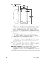
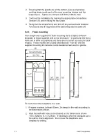
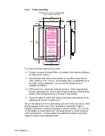
Do not use the Rear Casing as a template to drill the holes. Work
only from the marked positions.
2. Drill the holes in the vertical surface to suit the best method of
fixing.
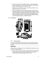
3. Ensure the Rear Casing is securely attached to the vertical surface
using the four 7mm diameter screw holes provided. No sealing
washers are necessary.
IMPORTANT: Do not use countersunk headed fixing screws. Only use
round head, socket cap head or pan head screws. Take care not to
over tighten the screws, doing so may damage the case, could
result in an unsafe condition and will invalidate your warranty.
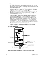
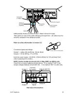
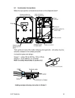
4. Continue the installation by making the appropriate connections
(section 6.5).
5. Reconnect the ringer. Secure the telephone Front Casing to the
Rear Casing.
5.3.2 Pole
mounting
Kit No 100-02-0208-001
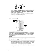
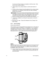
This accessory is for mounting GAI-Tronics telephones on to the side of
round poles of 100mm to 200mm (4 – 8in) diameter, or on to square or
rectangular section uprights of 100mm to 150mm (4 – 6in) across the
mounting surface. For flat mounting on surfaces greater than 150mm
(6in) across use the desk or wall mounted methods as appropriate.
NOTE:
Banding straps (large scale worm-drive clamps) are not included in this
kit and must be obtained separately. For details of where banding can
be obtained, refer to GAI-Tronics.
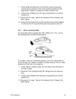
6. Remove rubber feet from the Rear Casing if fitted. Attach the pole
mounting clamp assemblies to the Rear Casing using the M6 x 25
screws provided.
Содержание Titan
Страница 29: ...29 VoIP Telephone 9 CE Declaration...
Страница 31: ...31 VoIP Telephone...


