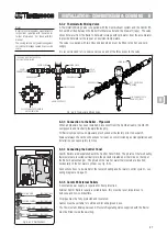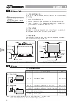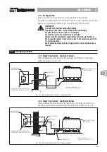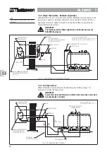
33
BALANCED FL
BALANCED FL
BALANCED FL
BALANCED FL
BALANCED FLUE 9
UE 9
UE 9
UE 9
UE 9
9-2
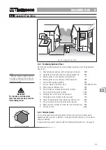
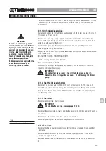
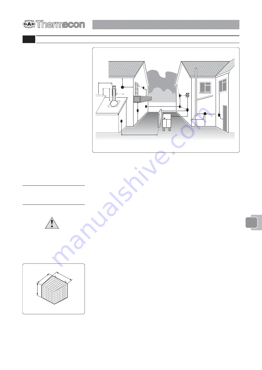
Suggested Flue Siting
G
G
N
J
H
C,D
L
A
K
F
G
E
A
B
B
C
C,D
B
F
P
F
M
O
CLOSER THAN 750
H
Fig. 9-2a Suggested Flue Siting
Note
*When the terminal is within 1 metre of
any plastic material this should be
protected from the effects of combustion
products of the flue.
9-2.1 Positioning Balanced Flues
Fig. 9-2a and the table below shows recommended clearances when siting balanced
flues for oil.
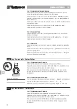
A Directly below an opening, airbrick, opening window etc.
600*
B Horizontal to an opening, airbrick, opening window etc.
600
C Below a gutter, eaves or balcony with projection
75
D Below a gutter, eaves or balcony without projection
600*
E From vertical sanitary pipework
300
F From an internal or external corner
300 /600
G Above ground or balcony level
300
H From a surface or a boundary facing the terminal
600
J
From a terminal facing the terminal
1200
K Vertically from a terminal on the same wall
1500
L Horizontally from a terminal on the same wall
750
M Above the highest point of an intersection with the roof
600
N From a vertical structure to the side of the terminal
750
O Above structure less than 750 from the side of the terminal
600
P From an oil tank
1800
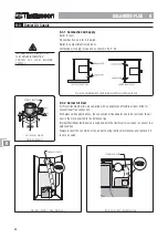
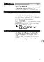
9-2.2 Terminal Guard
It is recommended that a terminal guard be fitted to low level flue terminals and in
applications where persons could come into contact with the terminal, or if it could be
subject to damage.
A special terminal guard is supplied with Free Standing External boilers - see page 57.
330
330
330
Fig. 9:2b Terminal Guard
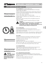
IMPORTANT
For situations and dimensions
other than those shown contact the
local building control.
99999
Nothern Ireland &
Republic of Ireland

