15
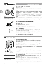
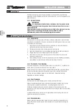
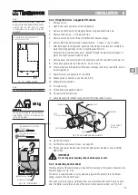
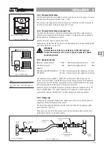
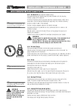
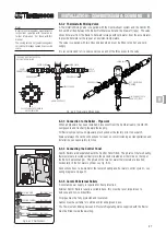
5-3.4 Fixing the Boiler - Suggested Procedure
1. Remove carton.
2. Open Boiler door and remove flue components.
3. Remove Control Panel by unplugging Burner plug and unbolt two nuts.
4. Remove main casing - 3 screws each side.
5. Remove access door and lift out all baffles from heat exchanger.
6. Remove Boiler body from wood transport blocks - 3 screws, 1 top, 2 bottom.
7. Offer back panel to the position required on the wall and use this as a template to
mark the drilling positions for the 3 mounting rawl bolts ‘R’.
Also mark the positions of any holes required through the wall for water pipes, oil
pipes, fire check valve and electric cable.
8. Remove panel and accurately drill required holes and fit 3 rawl bolts into holes ‘R’.
9. Place back panel onto the 3 rawl bolts - do not fit nuts.
10. Clear work space and carefully lift the heat exchanger onto the 3 rawl bolts, fit nuts -
do not tighten yet.
11. Adjust for level and tighten the 3 rawl bolts.
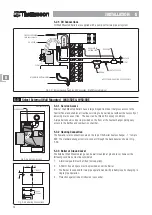
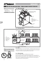
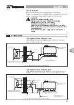
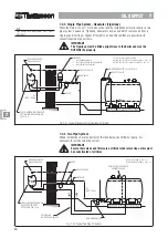
12. Make oil pipe connections, see Section 5-3.6.
13. Make water connections.
14. Fit main casing.
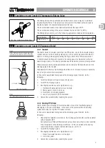
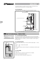
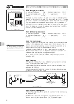
15. Fit flue bend with gasket to Boiler.
16. Fit seal inside flue terminal.
17. Lubricate seal with lubricant supplied and fit terminal with 4 screws.
INST
INST
INST
INST
INSTALLA
ALLA
ALLA
ALLA
ALLATION 5
TION 5
TION 5
TION 5
TION 5
Note
Before removing main case, study the
Burner position and the Boiler wall position
and decide on the best oil pipe
configuration, see Section 5-3.6 and
Section 7.
K x 2
R
R
R
K
R - 3 HOLES DRILL 12Ø FOR RAWL BOLTS
K - KNOCKOUT POSITIONS
Fig. 5-3c Drilling Positions
W
W
W
W
WARNING
ARNING
ARNING
ARNING
ARNING
The weight of the Boiler Heat Exchanger
bare is 50kg (110 lbs) - it is a two person
job to lift it in place.
Note
For back panel dimensions, see page 56.
50
50
50
50
50 kg
kg
kg
kg
kg
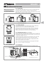
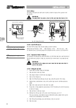
Fig. 5-3d External Boiler Flue Assembly
18. Re-fit Control Panel.
19. Re-fit Baffles and Access Cover - see page 39.
20. Finally, seal top and both sides externally with sealant provided - ensure GOOD
NEAT SEAL.
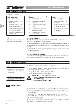
IMPORTANT
Do not trap phial capillary tubes behind access cover.
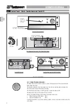
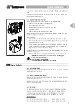
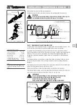
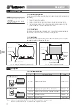
5-3.5 Connecting Control Panel
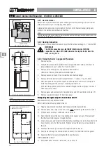
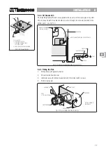
The three phials of the thermostats are inserted horizontally in the pockets situated in the
heat exchanger, see fig. 5-3e.
The Burner is supplied with a 4 wire cable and plug which connects into the Burner
supply socket on the Control Panel.
The mains electricity supply, preferably from a spur switched and fused 5 amp, should
enter the Boiler casing through one of the holes or knockouts provided, see Fig. 5-3c.
SEAL
FITTED INSIDE TERMINAL
SCREWS X 4
MAIN CASE
FLUE BEND
FLUE TERMINAL
GASKET
1
3
2
Fig. 5-3e Phial Positions
FROST STAT PHIAL
(NO SLEEVE)
POSITION 3
LIMIT AND CONTROL STAT PHIAL
POSITIONS 1 & 2
BURNER CABLE & PLUG
MAINS SUPPLY PLUG
FIT FLUE GUARD IF
APPLICABLE.
55555


