29
OIL SUPPL
OIL SUPPL
OIL SUPPL
OIL SUPPL
OIL SUPPLY 7
Y 7
Y 7
Y 7
Y 7
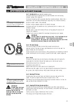
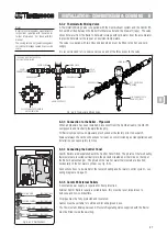
7-2.2 Oil Supply Pipe
In ALL oil systems the vertical lift of the oil line should be 10mm diameter.
Horizontal runs should also be 10mm diameter, however it is good practice to use 15mm
diameter, on the horizontal sections only, of pipe runs longer than 40 metres.
IMPORTANT
The filter must be fitted outside the Building.
Tigerloops, when fitted, must be fitted outside the building.
All joints in the oil line must be oil and air tight.
No soldered joints are permissible in supply pipe.
Always flush the complete oil supply before connecting to the Burner.
When specified always fit non-return valves in the position shown on the
oil system drawings.
Walls should be sleeved where oil pipes and fire valve capillaries pass
through.
7-3
Oil Supply System
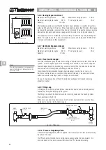
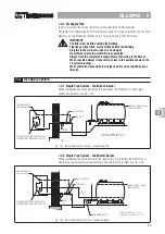
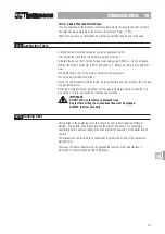
7-3.1 Single Pipe System - Tank Above Burner
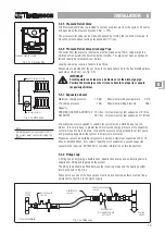
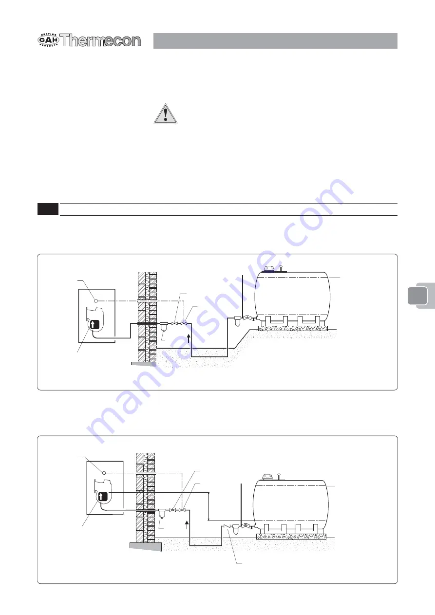
Where installations have the bottom of the tank above the Oil Burner, a single pipe
system can be used, see fig. 7-3a.
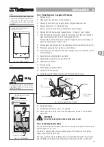
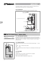
Fig. 7-3a Typical Single Pipe Oil System - Tank Above Burner
MAX. OIL LEVEL 4 metres
ABOVE BURNER
SHUT OFF VALVE
FILTER
THE OIL BURNER PUMP SHOULD BE SET
FOR SINGLE PIPE OPERATION, SEE 13-4.5.
FIRE VALVE SENSOR
FIXED ABOVE BOILER
FIRE VALVE
PLASTIC TANK SHOWN - SEE 7-1.2
STEEL TANK ALSO SUITABLE - SEE 7-1.3
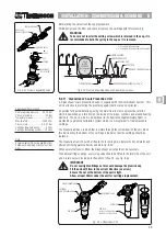
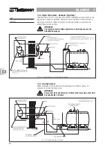
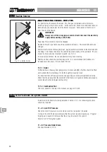
7-3.2 Single Pipe System - Tank Below Burner
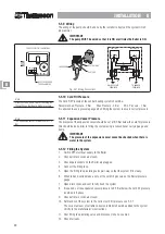
Where installations have the bottom of the tank up to 1 metre below the Oil Burner, a
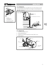
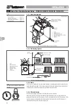
single pipe system can be used providing a non-return valve is fitted, see fig. 7-3b.
MAX. OIL LEVEL 4 metres
ABOVE BURNER
SHUT OFF VALVE
FILTER
THE OIL BURNER PUMP SHOULD BE SET
FOR SINGLE PIPE OPERATION, SEE 13-4.5.
FIRE VALVE SENSOR
FIXED ABOVE BOILER
FIRE VALVE
PLASTIC TANK SHOWN - SEE 7-1.2
STEEL TANK ALSO SUITABLE - SEE 7-1.3
LIFT UP
TO 1M
NON-RETURN VALVE
Fig. 7-3b Typical Single Pipe Oil System - Tank Below Burner
77777

