11
INST
INST
INST
INST
INSTALLA
ALLA
ALLA
ALLA
ALLATION 5
TION 5
TION 5
TION 5
TION 5
5-1
Select and Option Internal Floor Standing
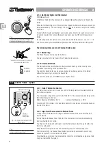
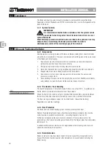
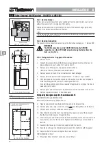
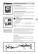
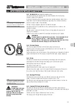
5-1.1 Service Access
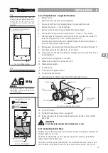
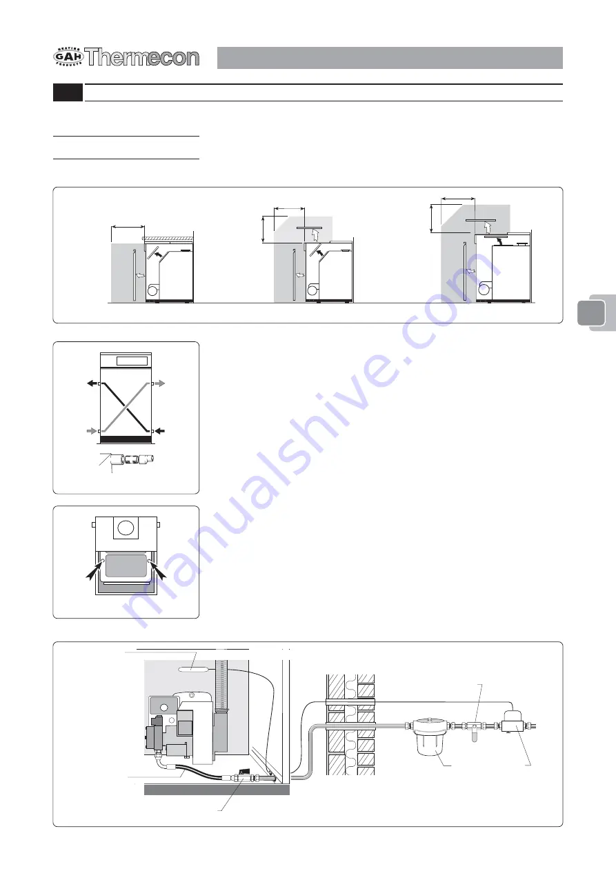
Boiler Models 40/65, 60/80, 80/95 and 90/120 can have the heat exchanger serviced
from both the front or top of the Boiler. The Burner is serviced from the front.
Boiler Models 100/150, 140/190, 190/240 and 240/
270
require top access for servicing
the heat exchanger. The Burner is serviced from the front.
Note
For Boiler dimensions see Section 13.
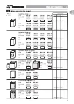
Fig. 5-1a shows recommended access.
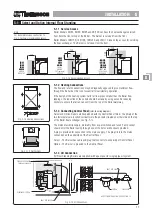
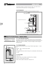
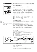
5-1.2 Heating Connections
The flow and return connections may be diagonally opposed to give maximum flow
through the Boiler but this is not essential for satisfactory operation.
If the design of the heating system calls for flow pipes smaller than the Boiler flow
tappings, the reduction of the outlets should be made by using excentric reducing
sockets to ensure that all air can vent from the top of the Boiler waterway.
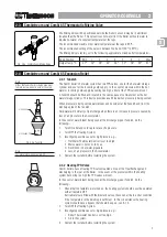
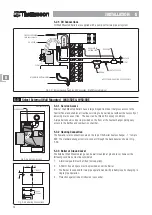
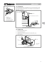
5-1.3 Connecting Control Panel
(refer to wiring diagram)
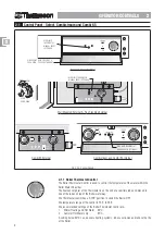
Select and Option Boilers are despatched with the Control Panel fitted. The phials of the
two thermostats are inserted vertically into the pockets situated on either side on the top
of the Boiler heat exchanger, see fig. 5-1c.
The mains electricity supply, preferably from a spur switched and fused 5 amp socket
should enter the Boiler casing through one of the holes or knockouts provided.
A plug is provided for connection to the mains supply. The plug fits into the mains
connection on the underside of the Control Panel.
Select - The Burner has cable and plug that connects to underside of Control Panel.
Option - The Burner is prewired to the Control Panel.
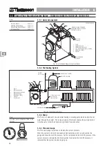
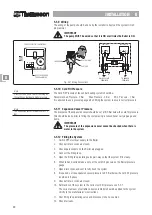
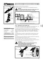
5-1.4 Oil Connection
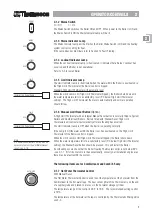
All Floor Standing Boilers are supplied with a pump set for single pipe oil system.
750
750
750
750
750
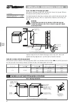
Fig. 5-1a Recommended Access
40/65
40/65
40/65
40/65
40/65
60/80
60/80
60/80
60/80
60/80
80/95
80/95
80/95
80/95
80/95
90/120
90/120
90/120
90/120
90/120
UNDER
WORKTOP
40/65
40/65
40/65
40/65
40/65
60/80
60/80
60/80
60/80
60/80
80/95
80/95
80/95
80/95
80/95
90/120
90/120
90/120
90/120
90/120
FRONT
AND/OR
TOP (optional)
ACCESS
100/150,
100/150,
100/150,
100/150,
100/150,
140/190,
140/190,
140/190,
140/190,
140/190,
190/240
190/240
190/240
190/240
190/240
240/270
240/270
240/270
240/270
240/270
FRONT AND
TOP ACCESS
REQUIRED
Fig. 5-1b Heating Connections
Fig. 5-1c Phial Positions
Fig. 5-1d Oil Connections
FIRE VALVE SENSOR
FIXED ABOVE BURNER
SHUT OFF VALVE
FILTER
✓
FIRE VALVE
✓
✓
SHUT OFF VALVE
✓
FLEXIBLE OIL PIPE
✓
✓
✓
SUPPLIED WITH BOILER - SEE SECTION 13.
55555


