background image

20

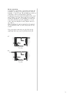
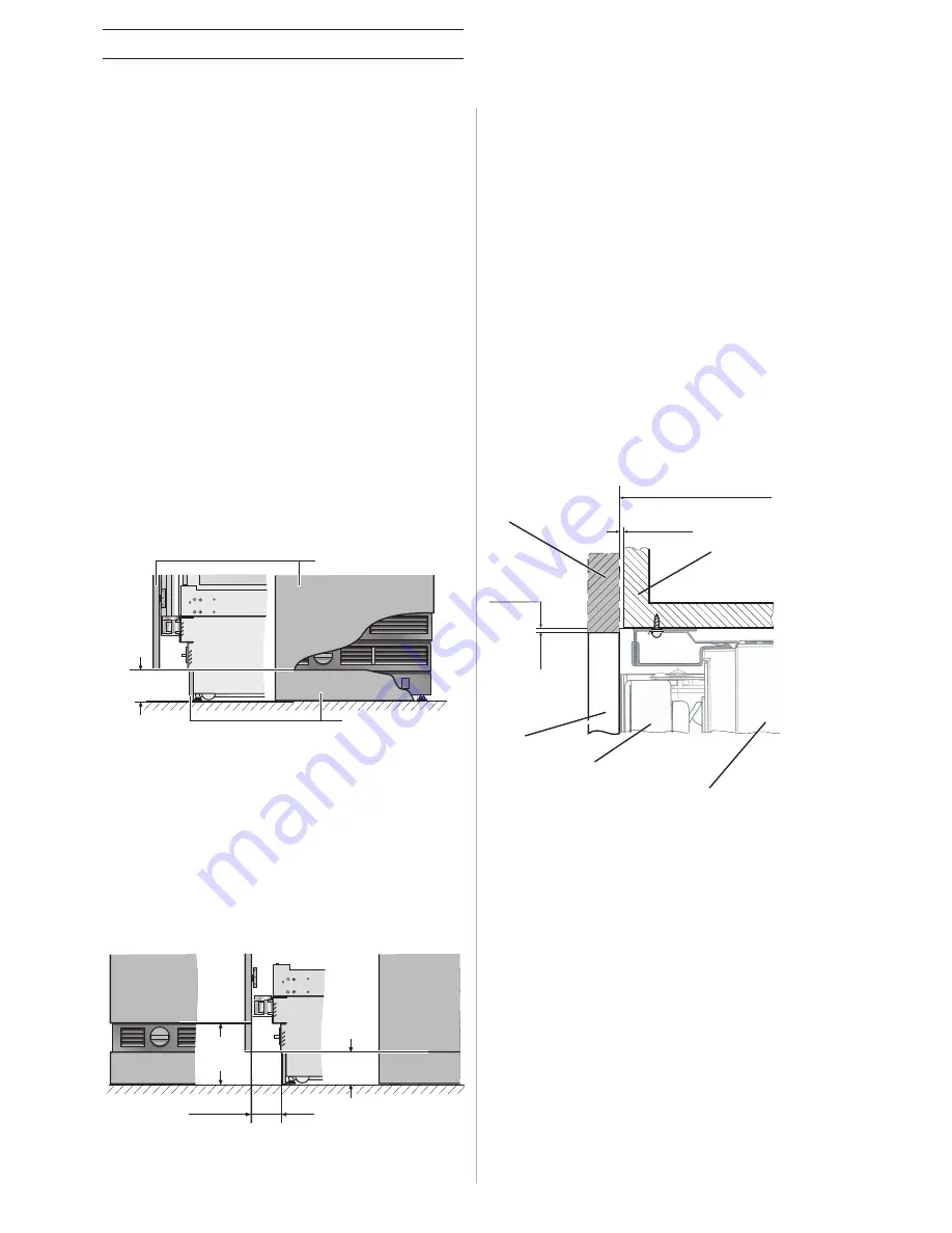
Base area/Crown of the niche

102

181

72 - 106

Base area

Crown

The height of the cabinet door on the appliance is
dependent on:
– the overall height of the appliance,
– the distance from the bottom edge of the cabinet

door to the floor,

– the appliance type (one-door or multi-door appli-

ances).

The overall height of the appliance is 2,134 mm.
The height can be adjusted within a range of 
-13 mm to +35 mm.
You must observe the minimum distance of 100 mm
between the upper edge of the floor and the bot-
tom edge of the cabinet door of the appliance.

This height can vary depending on the conditions
at the site.
It is possible, e.g. for design reasons, to lengthen
the cabinet door upwards by extending it beyond
the top of the appliance.

For design reasons, it may be necessary to in-
crease the distance between the upper edge of the
floor and the bottom edge of the cabinet door of
the appliance, so that it extends beyond the stan-
dard dimension of 102 mm. The maximum dimen-
sion is 181 mm.
If this is the case, air inlets and exhaust air outlets
and access to the water filter would become visi-
ble.

It must be ensured that the crown of the instal-
lation niche always has a depth of at least 
100 mm (measured from the front edge of the
appliance). Only then can the secure installation
of the appliance in the installation niche be
guaranteed.

G

Impor tant!

Poor ventilation leads to damage to the appliance.
Under no circumstances is it permitted to cover the
air inlets and the exhaust air outlets of the appli-
ance in the lower base area.
You must observe the minimum distance of 100 mm
between the upper edge of the floor and the bot-
tom edge of the cabinet door of the appliance.
Take this into consideration when adjusting the 
appliance feet also.

102

Cabinet door of 
the appliance

Plinth

3

3

102

Extending the 
cabinet door

Crown

Cabinet door of
the appliance

Appliance
door

Appliance body

In relation to the standard height, the maximum
height of the base board is 102 mm. The plinth can
be maximum 19 mm thick.
Adhesive connectors are supplied on the front
panel of the appliance for fitting the base board.
The air inlets and the exhaust air outlets of the 
appliance, as well as the access to the water filter
(if available) are located above the base board.
They must not be covered.

Содержание RB491200 - annexe 2

Страница 1: ...Gaggenau planning aid Vario Cooling appliances...

Страница 2: ...10 Appliance dimensions Wall clearance RB RY 11 Installation niche Dimensions 12 Special accessories Dimensions door fronts door front frames 13 Planning principle for an individual appliance 14 Plan...

Страница 3: ...3 Overview of Vario fridges Vario freezers Vario wine storage cabinets Niche 213 cm Ice Ice maker FC 0 C Fresh cooling close to 0 C W Wine D Ice and water dispenser...

Страница 4: ...ap per door Freezer zone Net volume 138 litres No frost technology with fast freezing Temperature adjustable from 14 to 25 C Four star freezer compartment Freezing capacity 23 kg 24 h Storage time aft...

Страница 5: ...t interior lighting with two ceiling spots and two halogen light pillars on the side Solid aluminium door racks One large bottle door rack Two height adjustable door racks One rack with front flap Fre...

Страница 6: ...with two ceiling spots Four solid aluminium door racks three of which are height adjustable one has a front flap Ice and water dispenser Illuminated ice and water dispenser with pull down flap accomod...

Страница 7: ...approx 1 5 kg 24 h Supply at normal operation approx 4 kg Planning note Flat hinge Door hinge left reversible The power socket can be planned behind the appliance Rating Total connected load 0 37 0 42...

Страница 8: ...ible The power socket can be planned behind the appliance Rating Total connected load 0 12 0 13 kW Connecting cable length 2 m with plug Vario wine storage and temperature control cabinet with two tem...

Страница 9: ...Vario cooling appliance RA 460 000 Accessory for side by side installation RA 460 011 Additional side heating element RA 460 020 Connecting element for vertically split appliance fronts for a flush fr...

Страница 10: ...mm 330 mm 76 2 cm 756 mm 690 mm 830 mm 363 mm 395 mm Notes The adjustable feet have an adjustment range of 35 mm to 13 mm The standard height displayed in the pictures is 0 mm For proper ventilation...

Страница 11: ...35 19 49 265 908 10 5 19 610 426 82 909 19 428 460 115 90 49 265 49 19 Notes The adjustable feet have an adjustment range from 35 mm to 13 mm The standard height displayed in the pictures is 0 mm For...

Страница 12: ...ase refer to the de tails given for individual appliances 350 25 59 2125 610 Y Y max 10 90 90 A B Appliance type Y 45 7 cm 224 mm 61 0 cm 304 mm 76 2 cm 380 mm 91 4 cm 458 mm A Area where the electric...

Страница 13: ...please ensure that the back of the cabinet door is visible to a height of 205 mm over the floor when opening the appliance door and adapt to the front design Appliance width 45 7 cm Maximum permitted...

Страница 14: ...ri ate crown to the niche The cabinet door for the appliance comes in an identical design to the other kitchen fronts Requirements for the installation niche The side walls of the installation niche m...

Страница 15: ...crown for the niche The cabinet door for both appliances comes in an identical design to the other kitchen fronts Requirements for the installation niche The side walls of the installation niche must...

Страница 16: ...door hinge of RW Side by Side solution with RY 491 RW 414 RY 491 Usability limitations Not all doors can be opened at the same time The left door of the RY may col lide with the handle of the RW Inst...

Страница 17: ...liances must be connected to each other before installation and pushed together into the installation niche Between RF 463 and RW to guarantee proper functioning of the finger pro tection of both appl...

Страница 18: ...ard rigid material The floor in the installation area must have the same height as the floor in the rest of the room Due to the heavy weight of a fully loaded appliance the floor beneath must be stabl...

Страница 19: ...e cold water supply The stop valve must not be located behind the appliance It is advisable to install the stop valve directly next to the appliance or in an other easily accessible location keywords...

Страница 20: ...d access to the water filter would become visi ble It must be ensured that the crown of the instal lation niche always has a depth of at least 100 mm measured from the front edge of the appliance Only...

Страница 21: ...dimensions and does not interfere with the finger protection The following special accessories are available for installing and configurating the appliance RA 460 040 Finger protection extra long If...

Страница 22: ...iency class A A A Annual energy consumption DIN EN 153 kWh 420 420 160 Daily energy consumption per 100 l of net volume kWh 0 22 0 22 0 09 Climate class SN ST SN ST SN ST Features Electronic temperatu...

Страница 23: ...610 762 610 610 457 610 457 608 608 608 608 608 608 608 175 208 167 167 136 173 143 195 189 186 186 155 191 162 555 483 401 401 300 571 377 1 381 365 443 417 320 294 340 314 237 211 422 394 296 275 3...

Страница 24: ...61 612 Stainless steel left hinged RA 461 613 Wine accessories Fully extendable bottle trays in beech and aluminium Fully extendable shelves in aluminium Presenter in aluminium for single bottle displ...

Страница 25: ...30 RA 421 130 RA 421 630 RA 421 730 RA 422 630 RA 422 630 RA 421 111 RA 421 611 RA 421 112 RA 421 612 RA 421 131 RA 421 631 RA 421 132 RA 421 632 RA 461 712 RA 461 110 RA 461 610 RA 461 710 RA 461 614...

Страница 26: ...Gaggenau Hausger te GmbH Carl Wery Stra e 34 D 81739 M nchen www gaggenau com 9000300552 8708...

Отзывы: