14
Governors America Corp. © 2021 Copyright All Rights Reserved
EEG7500 Enhanced Electric Governor 8-2021-A8 PIB5115
actuator Type
Proportional
motor
c
ontrol
m
ode
Non-Feedback Speed Control
Default Mode
Feedback Speed
Control
Positioner
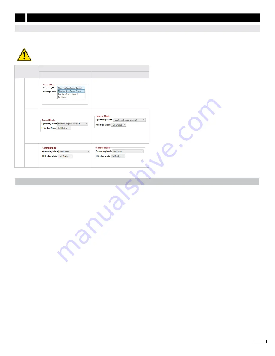
Settings in GAConfig Tool must match the actuator type. Actuators use one of three operating control modes:
. These feedback modes are further divided into half and full
(2)
bridge modes.
1.
Actuators are connected Terminals A and B as
diagrams. An
actuator with a position feedback sensor is required
to use the GAConfig Tool settings feedback speed
control or positioner mode.
2.
If control mode is changed, cycle power to the
EEG7500 controller for the change to take effect.
The default setting is Non-Feedback Speed Control
(NFSC). No other parameter settings need to have
the power cycled.
3. Positioner Mode is further defined in
of
this manual.
(1)
Half-bridge connects an output pin to either VCC (voltage
common collector), ground, or disconnects. Use half-bridge
to turn a DC motor on or off, or apply braking. Do not use it to
reverse the motor. Half bridge mode requires an actuator with a
spring to return to the original setting.
(2)
Full bridge control drives the actuator both ways and does not
require a spring in the actuator.
If H-Bridge Mode is set to Half Bridge, but the actuator does not support half bridge
, attempting to run the engine may harm
the engine or actuator. The information in the
is based on using a Non-Feedback Speed Control actuator.
SeLecTInG acTUaTor conTroL moDe
9
INITIAl SYSTEM SETUP
(conTInUeD)
DefaULT I / o DevIce maPPInG
The EEG7500 controller pairs device input mapping of signals physically connected to the EEG with various input and output parame
-
ters. The controller supports 5 analog and 2 digital inputs, and 1 analog and 3 digital outputs. Physical inputs are mapped to the param
-
eter settings in the GAConfig Tool.
Each physical connection made to the controller terminals must be mapped using the I/O Configuration screen of the GAConfig Tool.
The
table shows the terminal to input/output mapping. The following details the GAConfig Tools corresponding map
-
pings.
The Physical Input Mapping block in the I/O Configuration menu of the GAConfig Tool allows you to map each hardware device to a spe
-
cific use, assigning analog or digital signals to a specific input or output. The tool offers the flexibility to assign different input parameters
for various applications. Review the default I/O Configuration parameters and note the following:
•
Actuator is wired to Terminals A and B
•
Speed A and Speed B defaults are set to be wired as Digital Input 1 and Digital Input 2 (Terminals 3 and 4)
•
Variable Speed Input is mapped to Analog Input 1 (Terminal 7)
•
This input combination sets Selected Speed Mode as 1 (shown in Quick Access). Speed Mode 1 = idle.


