Furuno FCV-38 Скачать руководство пользователя страница 18

1.  MOUNTING

1-10

1.5

Junction Box (Option)

If the length of cable between the transducer and transceiver unit is more than 15 m, 
the optional junction box CV-304 (with 10 m, 20 m or 50 m cable) can be used for cable 
extension.

Keep in mind the following points when 
selecting a location.

•  Leave sufficient space at the sides and 

rear of the unit to facilitate mainte-
nance.

•  A magnetic compass will be affected if 

the junction box is placed too close to 
the magnetic compass. Observe the 
compass safe distances in "SAFETY 
INSTRUCTIONS" on page i to 
prevent 
interference to a magnetic compass.

•  Connect a copper strap (local supply) 

to the ground terminal.

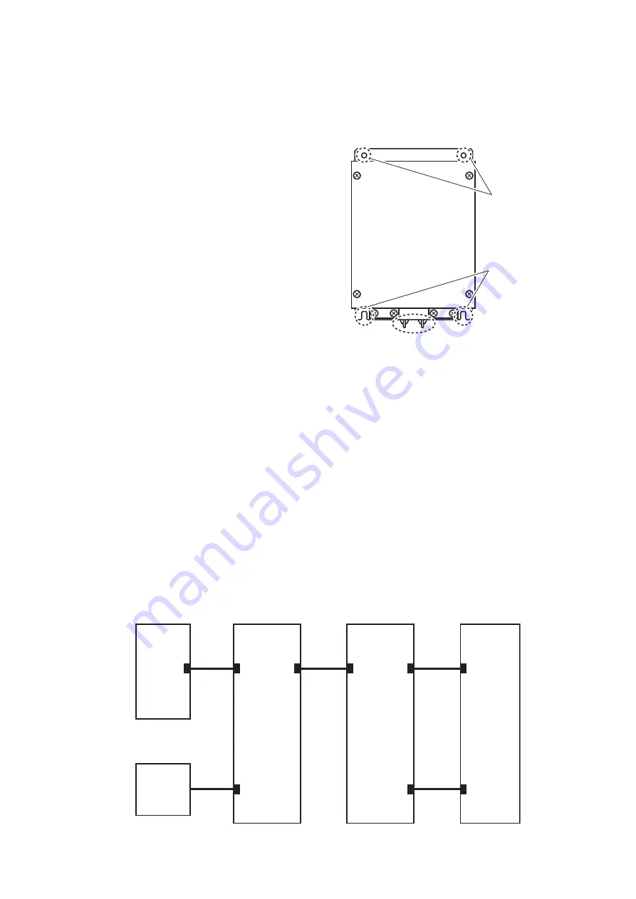
Use four bolts (M5, local supply) to secure the junction box.

For bulkhead mounting, fasten two bolts for the lower notches, leaving 5 mm of thread 
exposed from the bolt head. Set the notches of the junction box on the two bolts, the 
fasten two bolts for the upper bolt holes. Secure the junction box in place with all four 
bolts fastened tightly.

Note: 

For bulkhead installations, the cable entry must face downwards.

1.6

DVI/USB Repeater (Option)

To extend the distance between the display unit and the processor unit/USB device, 
use the optional DVI/USB repeater. Cable extension without the repeater can result in 
signal loss and incorrect data display.

The DVI/USB repeater has two units, one transmitter unit and one receiver unit. The 
following figure shows the general connection for the DVI/USB repeater.

Notches

Ground terminal

Bolt holes

USB 

Device

(Max. 

2 units)

Monitor 

Unit

DVI/USB 

Repeater 

Receiver 

Unit

DVI/USB 

Repeater 

Transmitter 

Unit

Processor 

Unit

HDMI

USB
(Type A)

USB

(Type B)

DVI

LAN

LAN

DVI

DVI

USB
(Type A)

Содержание FCV-38

Страница 1: ... 1 2 1 Processor unit 2 2 2 2 Transceiver Unit 2 6 2 3 Trackball Control Unit 2 8 2 4 Transducer 2 10 2 5 Junction Box option 2 11 2 6 DVI USB Repeater Option 2 13 2 7 Input Output Sentences NMEA0183 2 14 3 INITIAL SETTINGS 3 1 3 1 How to Set the Language and Measurement Unit 3 1 3 2 How to Set the Service Menu 3 2 3 3 Communication Port Setting 3 7 3 4 External Echo Sounder Setting 3 10 3 5 Calib...

Страница 2: ...7KH SDSHU XVHG LQ WKLV PDQXDO LV HOHPHQWDO FKORULQH IUHH 85812 XWKRUL HG LVWULEXWRU HDOHU VKLKDUD FKR 1LVKLQRPL D 3 1 6 3 3ULQWHG LQ DSDQ OO ULJKWV UHVHUYHG 3XE 1R 0 08 9 ...

Страница 3: ...age to the ship s hull For wooden or FRP vessel using a steel tank attach a zinc plate to the hull to prevent electrolytic corrosion Electrolytic corrosion can in the worst case result in loss of the transducer Be sure no water leaks in at the transducer mounting location Water leakage can sink the vessel Also confirm that the transducer will not be loosened by ship vibrations The installer of the...

Страница 4: ...the cable away from locations where it may be damaged during the installation Do not carry the transducer using only the cable The cable may become damaged or disconnected Do not shorten the transducer cable Do not paint the cable The cable sheath is made of chloroprene or vinyl chloride which are easily dam aged by plastic solvents such as toluene Locate the cables away from plastic solvents Do n...

Страница 5: ...red 3 To extend the distance between the processor unit and the monitor unit USB device use the optional DVI USB repeater 4 The transceiver unit CV 302 for FCV 30 is available Rectifier Unit RU 1746B 2 or AC DC Power Supply Unit PR 241 Standard supply Optional or local supply External KP Trackball Control Unit RCU 026 Trackball Control Unit RCU 026 12 24 VDC NMEA 0183 port 5 ports NETWORK2 port NE...

Страница 6: ...Spare Parts SP02 06001 001 569 280 1 For processor unit SP03 17661 001 249 760 1 For transceiver unit Name Type Code No Remarks Junction Box CV 304 10 10 m cable CV 304 20 20 m cable CV 304 50 50 m cable Rectifier Unit RU 1746B 2 000 030 439 AC DC Power Supply Unit PR 241 000 037 820 Cable Assembly HDMI TO DVI L 10 3M 001 407 170 HDMI cable be tween proces sor unit and display unit 10 3 m HDMI TO ...

Страница 7: ...P10 10150 000 036 722 100 m DVI USB Repeater TM000 FDX06_TXRX_30M 001 578 110 TX RX units w LAN cable 30 m TM000 FDX06_TXRX_50M 001 578 170 50 m TM000 FDX06_TXRX_100M 001 578 180 100 m TM000 FDX06_TXRX 001 578 190 TX RX units TM000 FDX06_RX 001 578 120 RX unit TM000 FDX06_TX 001 578 130 TX unit Cable Assembly MJ A3SPF0024 035C 000 157 943 10 RNS 08 132 001 107 540 10 5 m cable between DVI USB repe...

Страница 8: ...EQUIPMENT LISTS vi This page is intentionally left blank ...

Страница 9: ...g location is strong enough to support the weight of the unit Referring to the outline drawings at the back of this manual allow sufficient space for maintenance and service A magnetic compass will be affected if the unit is placed too close to the magnetic compass Observe the compass safe distances at the front of this manual to prevent interference to a magnetic compass For bulkhead installation...

Страница 10: ...n the mounting location for mounting bolts M6 20 supplied referring to the outline drawing at the back of this manual 2 Screw two hex head slot bolts into the lower pilot holes Leave 5 mm of thread vis ible 3 Set the notches of the unit onto the screws fastened at step 2 4 Screw two hex head slot bolts into the upper fixing holes 5 Fasten all screws tightly to secure the unit in place Hex head slo...

Страница 11: ...fter instal lation compensate for installation angle error referring to chapter 3 Deck Mount 1 If necessary install a channel base on the mounting location consulting with the shipyard Note Take account of the direction of the transceiver unit Position the transceiv er unit so that the left side faces the bow as viewed from the cover side 2 Drill four pilot holes in the mounting location for mount...

Страница 12: ...wings at the back of this manual allow sufficient space for maintenance and service Select a mounting location considering the length of the cables to be connected to the unit A magnetic compass will be affected if the unit is placed too close to the magnetic compass Observe the compass safe distances at the front of this manual to prevent interference to a magnetic compass Select a location where...

Страница 13: ...ntrol unit without the desktop fixing plate to install the unit flat on the desktop 1 Drill four mounting holes of 4 mm diameter referring to the outline drawings at the back of this manual 2 Secure the unit with the four washer head screws M3 12 supplied from the un derside of the desktop Self tapping screw ø5 20 2 pcs Washer head screw M3 12 4 pcs ...

Страница 14: ...n the mounting location referring to the outline drawing at the back of this manual 2 Set the unit to the mounting hole 3 Attach the four FM fixing plates to the unit from the rear side using the washer head screws M3 8 4 Fasten each wing bolt until the protector for the screw is firm against the mounting panel 5 Fasten each wing nut tightly to secure the unit FM fixing plate 4 pcs Washer head scr...

Страница 15: ...e same frequency by 2 5 m or farther Install the transducer face parallel to the sea surface Orient the transducer bow mark to ship s bow within 5 degree It is known that air bubbles are fewest at the place where the bow first falls and the next wave raises at usual cruising speed In small slow speed boats the position between 1 3 and 1 2 of the ship s length from the bow is usually a good place R...

Страница 16: ...er Coat casing with same paint as used on the ship s hull Methods to remove lacquer primer from the tank 1 Dissolve and remove paint with solvent 2 Remove rust coating oil film etc with a blaster 3 Remove with a disk sander or foil brush 1 4 2 Transducer fixing plate kit option assembly You can use the optional T 625 A transducer fixing plate kit to reduce noise caused by ship movement for transdu...

Страница 17: ...the sponge in place with a hose clamp stainless band Apply silicone sealant local supply to the screws to prevent seizing and corrosion 4 Refit the press plate as before Tighten the double nuts at 63 5Nm torque 5 To attach to the ship s bottom refer to the T625 tank drawing TD attachment Insert the uncut part between the transducer and the TD attachment Flank sponge Stainless band Silicone sealent...

Страница 18: ...sten two bolts for the lower notches leaving 5 mm of thread exposed from the bolt head Set the notches of the junction box on the two bolts the fasten two bolts for the upper bolt holes Secure the junction box in place with all four bolts fastened tightly Note For bulkhead installations the cable entry must face downwards 1 6 DVI USB Repeater Option To extend the distance between the display unit ...

Страница 19: ...w sufficient space for maintenance and service A magnetic compass will be affected if the unit is placed too close to the magnetic compass Observe the compass safe distances at the front of this manual to prevent interference to a magnetic compass For bulkhead installations secure the unit so that the cable entrance faces down ward The maximum cable length for the video signal cable is as follows ...

Страница 20: ...to the outline drawing at the back of this manual 2 Screw the four self tapping screws into the pilot holes Leave 5 mm of thread vis ible 3 Hang the unit onto the screws fastened at step 2 4 Fasten all screws tightly to secure the unit in place Self tapping screw ø5 20 4 pcs Detailed view Hang on the unit onto the self tapping screws ...

Страница 21: ...If you do not use the USB port on the RCU 026 the USB connection between the RCU 026 and processor unit is not required 3 To install the processor unit apart from the monitor unit and USB device use the optional DVI USB repeater 4 The transceiver unit CV 302 for FCV 30 is available USB2 0 2 ports max 5 m USB3 0 2 ports max 3 m 100 110 115 220 230 VAC 1ø 50 60Hz Display Unit 3 USB device䠆2 Standard...

Страница 22: ... device operation is not guaranteed USB2 0 Max 5 m USB3 0 Max 3 m USB2 0 12 24 VDC Not used NETWORK1 To Transceiver Unit Note Use LAN1 port for connection with the Transceiver Unit HDMI2 To Monitor Unit Sub HDMI1 To Monitor Unit Main USB4 2 USB3 0 USB2 2 USB3 2 USB1 2 USB3 0 USB2 0 POWER For DFF3 Ground Terminal Cable entrance HDMI cable or HDMI TO DVI L 5 3 10 3 m USB cable DTICE350SLABVCVXXT 1 M...

Страница 23: ...e 1 TB3 NMEA0183 equipment TTYCSLA 4 1 2 TB4 3 TB5 4 TB6 5 TB7 6 to 7 Not used 8 J1 Control unit 9 J2 Control unit 10 to 12 Not used 1 2 3 4 5 6 7 10 11 12 8 9 TB3 TB4 TB5 TB6 J1 TB7 J2 Secure each cable to the wiring clamp Terminal opener Cable clamp Fasten the crimp on lug drain wire of the TTYCSLA cable 10P7099 The entrance numbers with are not used PIF board 10P7099 DIP switch DIP SW S1 1 S1 2...

Страница 24: ...heath and cut it leaving approx 9 mm 25 mm approx 9 mm approx 9 mm approx 11 mm Fold back drain wire and cut it leaving approx 9 mm Straighten and flatten the cores in colored order and cut them leaving approx 11 mm Modular plug Using special crimping tool MPT5 8AS PANDUIT CORP crimp the modular plug Finally check the plug visually Insert the cable into the modular plug so that the folded part of ...

Страница 25: ...ner sheath 6 mm 6 mm 6 mm 6 mm Attach a crimp on lug FV1 25 3 supplied locally to the core Vinyl tape Drain wire Drain wire Pass a heat shrinkable tube supplied locally onto the drain wire Procedure 1 Twist the cores 2 Press the terminal opener downward 3 Insert the wire in the hole 4 Remove the terminal opener 5 Pull the wire to confirm that it is secure Press downward Terminal connector Terminal...

Страница 26: ...o attach the terminal block connector see page 2 5 Power cable DPYCSLA 1 5 70 䡉䡉 70 䡉䡉 230 䡉䡉 230 䡉䡉 Cable jacket Armor Inner vinyl sheath Attach the modular plug Outer vinyl sheath Vinyl tape Clamp position 400 mm 400 mm Armor Vinyl tape 6 mm 6 mm Clamp position Attach supplied crimp on lugs FV 5 5 to the cores 100 mm 100 mm Armor Vinyl tape Clamp position ...

Страница 27: ...ower cable Clamp at the armored section of the cable 4 Connect the following cables to the appropriate connectors referring to the wiring label attached on the back of the cover Transducer cable Connect the connectorsTRX1 to TRX4 on the cables to the connectors CN B101 to B104 on the chassis via appropriate wiring clamp LAN cable Connect to LAN101 connector Cable for external KP Connect External K...

Страница 28: ...hip s ground Note 1 If the USB cable is connected to the trackball control unit fasten the USB ca ble to the cable tie mount using the supplied cable tie Note 2 The maximum cable length for USB2 0 is 5 m To extend the USB cable the optional DVI USB repeater is required If you extend the USB cable without the DVI USB repeater the USB device operation is not guaranteed Note 3 The supplied USB cable ...

Страница 29: ...e trackball control unit and the processor unit use the optional cable assembly 6TPSH XH12X2 LxxSP2 5 10 m 1 Unfasten four binding screws M3 8 from the bottom of the unit and a pan head screw M3 8 and flat washer from the back of the unit to remove the cover Note Remove the cover slowly to prevent damage to the cables connected to the circuit board in the unit USB sheet Attach this sheet when the ...

Страница 30: ... of the cable assembly with the cable clamp removed at step 2 then connect the connector at the end of the cable assembly to the J1 connector on the circuit board Note The shield of the cable must not touch the circuit board 6 Reattach the control unit cover 2 4 Transducer The transducer with a cable diameter 22 0 mm should be installed Check that the data sheet sticker on the transducer cable is ...

Страница 31: ...0 mm conductive tape is not required 2 5 Junction Box option Connect the ground wire between the ground terminal on the chassis and the ship s earth referring to section 1 5 How to open close the top cover Unfasten four screws to open the top cover from the junction box After the appropriate cable connections are completed replace the cover then fasten the four screws Cable Connection Unfasten the...

Страница 32: ...t Transducer cable Cable clamp TRX1 cable to J2 connector TRX2 cable to J4 connector TRX3 cable to J6 connector TRX4 cable to J8 connector TD1 cable to J1 connector TD2 cable to J3 connector TD3 cable to J5 connector TD4 cable to J7 connector ...

Страница 33: ... power a rectifier is required The LAN and USB cables must be fastened to the cable clamp using a cable tie sup plied locally After wiring reattach the protective cover Note The cable clamp for the USB and LAN cables can be adjusted to accommodate the connectors of those cables See the following figure Screws for protective cover Protective cover Receiver Unit Transmitter Unit Monitor Unit Not use...

Страница 34: ...ompany IIHFB Proprietary sentence of other company IIMTW Proprietary sentence of other company IITPC Proprietary sentence of other company IITPT Proprietary sentence of other company MPMSD Proprietary sentence of other company pireq FURUNO proprietary sentence SDDBS Proprietary sentence of the other company SDfnz FURUNO proprietary sentence Output sentences DBS Depth below surface Ver 1 5 DBT Dept...

Страница 35: ...l control on any section of the screen 3 Select the Advanced Settings icon from the In stantAccess bar to expand the Advanced Settings menu bar 4 Select the Advanced Settings icon from the Menu bar The Advanced Settings menu window appears 5 Select User Interface Settings from the menu The user interface settings appear 6 Select the appropriate language from the Language item The setting languages...

Страница 36: ...y the Service menu 1 Select the Advanced Settings icon from the InstantAccess bar and se lect the Advanced Setting icon from the expanded menu bar 2 Select Service to expand the service menu The message Ask your dealer to change service settings appears 3 Press and hold the OK button for approx 10 seconds to open the service ad vanced menus Shared Settings Fish Size Setting and External Echo Sound...

Страница 37: ...ent and external sounder are displayed on main monitor Item Setting value Meaning Display Resolution Switching Auto default Show the resolution which is input from the connect ed display Manual Select the resolution manually for the following menu Display Resolution Display Resolution XGA default SXGA UXGA FullHD WUXGA Select the appropriate resolution for main monitor Note This menu is available ...

Страница 38: ...itor Display Switch ing Note 2 The display resolution setting is required when the monitor type is changed 3 2 3 Date and time setting Set the date and time on the Shared Settings menu Item Setting value Meaning Date Auto Adjust Off On default Select On to automatically adjust the date and time at system start up Select Off to manually adjust the date and time as required Date Setting YYYY MM DD E...

Страница 39: ...em reboot because the com munication between the processor unit and the trackball control unit is disconnected temporarily The buzzer is stopped after completing the system reboot Item Setting value Meaning TX Triggering In Trigger Off default On Select On to input the external KP control External Trigger Delay 0 to 200 default 0 Set the delay for the external KP 0 to 200 ms Item Setting value Mea...

Страница 40: ...t used Transducer Parameter3 100 00 to 100 00 default 0 00 step 0 01 When the Junction Box is used you can cali brate for cable attenuation Note If the optional junction box CV 304 50M is connected to this equipment this menu setting should be 1 8 Item Setting value Meaning IIMTW Sentence Off default Water Temp Meter ITI Net Sensor Select ITI Net Sensor if an ITI net sensor is connected Otherwise ...

Страница 41: ...0 default 15 5 step 0 1 Set gain increment dB at mid fre quency Hi 50 0 to 2 0 default 31 2 step 0 1 Set gain increment dB at high fre quency Processor Unit IP Address 1 to 254 default 7 Set the fourth octet of IP address 1 for the processor unit and the trans ceiver unit Note 1 The first to third octets are fixed to 172 31 2 Note 2 Each IP address must be unique between units Transceiver Unit IP ...

Страница 42: ...require appropriate external data input 9 Select a baud rate from 600 4800 or 38400 bps at Baud Rate then click the OK button to close the menu Note Select 38400 bps when the TLL Output is set to FURUNO TLL 4800 or 600 bps may slow the transmission of sentences 10 Push the OK button to close the port setting menu 11 Set the parameters for other port tabs referring to this procedure s steps 4 to 10...

Страница 43: ... VDVHW 9 00 T 9 0 M 99 9 N 94 K 6D GPVTG 100 0 T 20 M 11 2 N 1 2 K 52 GPMTW 013 75 C 04 VDVHW 9 00 T 9 0 M 99 9 N 94 K 6D GPVTG 100 0 T 20 M 11 2 N 1 2 K 52 GPMTW 013 75 C 04 VDVHW 9 00 T 9 0 M 99 9 N 94 K 6D GPVTG 100 0 T 20 M 11 2 N 1 2 K 52 GPMTW 013 75 C 04 VDVHW 9 00 T 9 0 M 99 9 N 94 K 6D GPVTG 100 0 T 20 M 11 2 N 1 2 K 52 Signal monitor area Update button ...

Страница 44: ... InstantAccess bar then se lect the Advanced Settings icon from the menu bar The Advanced Settings menu windows appears 2 Select Service to expand the service menu The message Ask your dealer to change service settings appears 3 Press and hold the OK button for approximately ten seconds to open the service advanced menu 4 Select the External Echo Sounder from the Service menu 5 Select DFF3 from th...

Страница 45: ...eters from the sub monitor The procedure assumes that External Fish Finder see page 3 3 has already been set to On Set the transducer s parameters from sub monitor window as belows Suppose the sub monitor is installed and the External Fish Finder Window see page 3 3 is set to On already 1 Select the Windows icon from the InstantAccess bar and press the Sub monitor icon to display the echo window o...

Страница 46: ... You can calibrate the main system s transducer and the external sounder s transducer 3 5 1 Calibration for main system transducer 1 Select the Advanced Settings icon from the InstantAccess bar and select the Advanced Setting icon from the expanded menu bar 2 Select Calibration from the System menu The Calibration menu appears 3 Set the calibration parameters referring to the table below Item Sett...

Страница 47: ...s displayed with a straight line making dis crimination of bottom fish easier However the bottom presentation may change de pending on gain setting When set to Color select the color 0 63 to be judged as the bottom echo Bottom level 40 to 40 default 0 Set the strength at which an echo is deter mined to be the bottom If the level is too low however it may be difficult to distinguish bot tom fish fr...

Страница 48: ...o 9 8 fm 0 7 to 1 6 HR 0 9 to 2 0 pb 0 8 to 1 8 The minimum value is default Adjusts the transmission line Refer the figure below this table Gain ADJ HF 50 to 50 default 0 Set the gain for high frequency of the Satellite Compass Gain ADJ LF 50 to 50 default 0 Set the gain for low frequency of the Satellite Compass TD fore aft 100 0 to 100 0 default 0 0 Fore aft distance m from antenna to transduce...

Страница 49: ...8 to 1 8 The minimum value is default Adjusts the transmission line Draft m 9 0 to 30 4 ft 30 0 to 99 9 fm 0 7 to 1 6 HR 0 9 to 2 0 pb 0 8 to 1 8 default 0 0 The default depth display shows the dis tance from the transducer Fish Size 80 to 100 default 0 Compensate for incorrect fish size indi cations Sound Speed 200 0 to 2000 0 default 1500 Calibration for speed of sound m s Item Setting values Me...

Страница 50: ... Settings icon from the InstantAccess bar and select the Advanced Setting icon from the expanded menu bar 2 Select Stabilization menu from the System menu The Stabilization menu appears 3 Set the calibration parameters referring to the table below Item Setting values Meaning Stabilization Off default On Set to On to enable the stabilization mode Turn this function on when seas are rough to get sta...

Страница 51: ...ansducer Enter a positive value for a fore side transducer TD port stbd 100 0 to 100 0 default 0 0 Port starboard distance m from antenna to transducer Enter a positive value for a starboard side transducer ANT TD height 0 0 to 100 0 default 0 0 Vertical distance m between the antenna and the transducer For Motion Sensor selecting at Motion Sensor Select Roll Offset 10 0 to 10 0 default 0 0 Set th...

Страница 52: ... ms Format SC 50 110 only IEC Ed 1 3 6 2 Stabilization for external sounder transducer Set the stabilization menu for external system transducers when External sounder is set On 1 Move the cursor onto the sub monitor and right click on the screen The setting menu for external sounder appears 2 Select Stabilization from the list on menu The Stabilization menu appears 3 Set the stabilization paramet...

Страница 53: ...ed at the drop down box on the screen SB Split beam B1 to B5 Beam 1 to Beam 5 Rx Test Receiving test 5 Press the wheel on the trackball to take a still image 6 Click the Close button to close the RX monitor screen 7 Press and hold the scrollwheel on the trackball control unit to open the replay screen then confirm that the still image that of the RX monitor screen is saved cor rectly 3 8 Reset to ...

Страница 54: ...ed Settings icon from the expanded menu bar 2 Select Service from the menu and press and hold the OK button for approxi mately ten seconds The Service menu is expanded 3 Select Restore Default Settings at the left bottom corner of the window The message window shown above appears 4 Select Yes to restart the system 3 9 Retrofit from FCV 30 If the transceiver unit of the FCV 30 is connected to the p...

Страница 55: ...ss as follows 1 Click the Windows mark at the bottom left of the screen and then select Win dows System Tools Control Panel 2 Click Network and Sharing Center 3 Click Change adapter settings 4 Right click Wi Fi or Ethernet and then select Properties 5 Select Internet Protocol Version 4 TCP IP v4 and then click Properties 6 Select Use the following IP address change the IP address and then click OK...

Страница 56: ... the default value and then click Apply 4 When the IP address is changed properly the message IP setting is completed appears above the progress bar Click Quit to quit the tool 5 The following message appears Click OK Note You do not have to change the Subnet mask IP address of FCV 30 transceiver unit Enter IP address of FCV 38 Information OK Please set the IP address subnet mask for Processor uni...

Страница 57: ...sor unit and the FCV 30 transceiver unit the setting is correct Note If system error T01 is shown the connection is wrong Check the Transceiver Unit IP Address setting of the FCV 38 processor unit and the IP address set in the transceiver unit 3 9 6 How to change the future IP address If you change again the IP address of the FCV 30 transceiver unit while using it nor mally after changing the IP a...

Страница 58: ...3 INITIAL SETTINGS 3 24 This page is intentionally left blank ...

Страница 59: ...11mm 12 6mm TTYCY 4 0 75mm2 1 11mm 17 7mm TTYCY 4SLA 0 75mm2 1 11mm 19 5mm TTYCYSLA 1 0 75mm2 1 11mm 11 2mm TTYCYSLA 4 0 75mm2 1 11mm 17 9mm EX TTYCYSLA 4 MPYC 4 Designation type of twisted pairs Designation type of cores 1 2 3 4 5 6 1 2 3 4 Cables listed in the manual are usually shown as Japanese Industrial Standard JIS Use the following guide to locate an equivalent cable locally JIS cable name...

Страница 60: ...0 7 5 6 3 䠄 ᅗ䛾ᑍἲ䛿䚸ཧ 䛷䛩䚹㻌㻌㻰㻵㻹㻱㻺㻿㻵㻻㻺㻿㻌㻵㻺㻌㻰㻾㻭㼃㻵㻺㻳㻌㻲㻻㻾㻌㻾㻱㻲㻱㻾㻱㻺㻯㻱㻌㻻㻺㻸㼅㻚䠅 A 2 㧼 㧼㧭㧯㧷㧵㧺㧳 ޓ 㧸㧵㧿㨀 4 7 0 1 7 6 0 5 4 26 10 1 ͳ 3 6 70 6 㩎㩡㨹㩂㩘㩨㨺㩣ᠲ ㇱ 64 10641 70 6 4 7 ઃዻຠ 5514 5 ઃዻຠ 5514 5 2 Ꮏ ᢱ 056 6 10 6 4 5 㩃㨺㩖㩨㩣 㩂㩚㩕㩧 75 55 65 Ꮏ ᢱ 056 6 10 6 4 5 2 䍘㪄䍢䍼 ภᧃየ䈱㪲㪁㪁㪴䈲䇮ㆬᛯຠ䈱ઍ 䍘䍎䍢䍼䉕 䈚䉁䈜䇯 㪚㪦㪛㪜㩷㪥㪬㪤㪙㪜㪩㩷㪜㪥㪛㪠㪥㪞㩷㪮㪠㪫㪟㩷㩹㪁㪁㩹㩷㪠㪥㪛㪠㪚㪘㪫㪜㪪㩷㪫㪟㪜㩷㪚㪦㪛㪜㩷㪥㪬㪤㪙㪜㪩㩷㪦㪝㩷㪩㪜㪧㪩㪜㪪㪜㪥㪫㪘㪫㪠㪭㪜㩷㪤㪘㪫㪜㪩㪠㪘㪣㪅 䋨 䈱ኸᴺ䈲䇮ෳ ୯䈪䈜䇯㩷㩷㪛㪠㪤㪜㪥㪪㪠㪦㪥㪪㩷㪠㪥㩷㪛㪩㪘㪮㪠㪥㪞㩷㪝㪦㪩㩷㪩㪜㪝㪜...

Страница 61: ... 1 25 5 5 1 21 㸧 㹄㹓㹐㹓㹌㹍ࠉ㹃㹊㹃㹁㹒㹐㹇㹁ࠉ㹁㹍ࠉ㸬㸪㹊㹒㹂 0 A 6 2 12 7 3 3 ࠉࠉᅗ 287 1 ྡࠉࠉ 1 0 ᩘ㔞 4 7 㸭ഛ 5 0 5 6 ྕ 12 ᆺྡ㸭つ᱁ 6 5 37 216 167 7 21 0 7 5 6 ᕤ ᮦᩱ 8 ᅽ Ꮚ 5 03 21 8 9 6 2 12 ᑟ㟁ᛶ㺡㺎㺪㺽 21 8 7 9 7 3 12 0 2 12 㸦 ᅗࡢᑍἲࡣࠊཧ ࡍࠋࠉ 0 16 216 1 5 1 25 5 5 1 21 㸧 㹄㹓㹐㹓㹌㹍ࠉ㹃㹊㹃㹁㹒㹐㹇㹁ࠉ㹁㹍ࠉ㸬㸪㹊㹒㹂 0 A 7 2 12 7 3 3 ࠉࠉᅗ 287 1 ྡࠉࠉ 1 0 ᩘ㔞 4 7 㸭ഛ 5 0 5 6 ྕ 12 ᆺྡ㸭つ᱁ 6 5 37 216 167 7 21 0 7 5 6 ᕤ ᮦᩱ 1㺗㺎㺪㺼㺷 7 66 0 7 6 9 9 7 2 12 㺘㺦㺖㺞 㺱㺚㺼㺋㺵㺎...

Страница 62: ...㺎 02 8 5 211 725 036 2 12 㸦 ᅗࡢᑍἲࡣࠊཧ ࡍࠋࠉ 0 16 216 1 5 1 25 5 5 1 21 㸧 㹄㹓㹐㹓㹌㹍ࠉ㹃㹊㹃㹁㹒㹐㹇㹁ࠉ㹁㹍ࠉ㸬㸪㹊㹒㹂 0 A 10 2 12 7 3 3 ࠉࠉᅗ 287 1 ྡࠉࠉ 1 0 ᩘ㔞 4 7 㸭ഛ 5 0 5 6 ྕ 12 ᆺྡ㸭つ᱁ 6 5 37 216 167 7 21 0 7 5 6 ᕤ ᮦᩱ 1㺗㺎㺪㺼㺷 7 66 0 7 6 9 9 7 2 12 㺘㺦㺖㺞 㺱㺚㺼㺋㺵㺎 02 8 5 211 725 036 2 12 㸦 ᅗࡢᑍἲࡣࠊཧ ࡍࠋࠉ 0 16 216 1 5 1 25 5 5 1 21 㸧 㹄㹓㹐㹓㹌㹍ࠉ㹃㹊㹃㹁㹒㹐㹇㹁ࠉ㹁㹍ࠉ㸬㸪㹊㹒㹂 0 A 11 2 12 7 3 3 ࠉࠉᅗ 287 1 ྡࠉࠉ 1 0 ᩘ㔞 4 7 㸭ഛ 5 0 5 6 ྕ 12 ᆺྡ㸭つ᱁ 6 5 37 216...

Страница 63: ...㪛㪬㪚㪫㪅㩷㪨㪬㪘㪣㪠㪫㪰㩷㪠㪪㩷㪫㪟㪜㩷㪪㪘㪤㪜㪅 A 14 㧼 㧼㧭㧯㧷㧵㧺㧳 ޓ 㧸㧵㧿㨀 2 0 1 7 6 0 5 4 26 10 1 ͳ 3 6 Ꮏ ᢱ 056 6 10 6 4 5 0㩃㨺㩖㩨㩣 6 55 6 8 8 㩄㩒㩂㩊 㩝㩆㩨㨷㩡㨺 1 7 4 100 614 25 䋨 䈱ኸᴺ䈲䇮ෳ ୯䈪䈜䇯㩷㩷㪛㪠㪤㪜㪥㪪㪠㪦㪥㪪㩷㪠㪥㩷㪛㪩㪘㪮㪠㪥㪞㩷㪝㪦㪩㩷㪩㪜㪝㪜㪩㪜㪥㪚㪜㩷㪦㪥㪣㪰㪅䋩 ဳᑼ㪆䍘䍎䍢䍼 ภ䈏䋲Ბ䈱႐ว䇮ਅᲑ䉋䉍 Ბ䈮ઍ䉒䉎ㆊᷰᦼຠ䈪䈅䉍䇮䈬䈤䉌䈎䈏 䈦䈩䈇䉁䈜䇯䇭䈭䈍䇮ຠ 䈲ᄌ䉒䉍䉁䈞䉖䇯 㪫㪮㪦㩷㪫㪰㪧㪜㪪㩷㪘㪥㪛㩷㪚㪦㪛㪜㪪㩷㪤㪘㪰㩷㪙㪜㩷㪣㪠㪪㪫㪜㪛㩷㪝㪦㪩㩷㪘㪥㩷㪠㪫㪜㪤㪅㩷㩷㪫㪟㪜㩷㪣㪦㪮㪜㪩㩷㪧㪩㪦㪛㪬㪚㪫㩷㪤㪘㪰㩷㪙㪜㩷㪪㪟㪠㪧㪧㪜㪛㩷㪠㪥㩷㪧㪣㪘㪚㪜㩷㪦㪝㩷㪫㪟㪜㩷㪬㪧㪧㪜㪩㩷 㪧㪩㪦㪛㪬㪚㪫㪅㩷㪨㪬㪘㪣㪠㪫㪰㩷㪠㪪㩷㪫㪟㪜㩷㪪㪘㪤㪜㪅 A ...

Страница 64: ... 575 1 01 㧔 ߩኸᴺߪ ޔ ෳ ୯ߢߔ ޓޕ 05 105 0 4 9 0 14 4 4 0 10 㧕 㧲㨁㧾㨁㧺㧻 ޓ 㧱㧸㧱㧯㨀㧾㧵㧯 ޓ 㧯㧻 ޓ 㧚㧘㧸㨀㧰 ဳᑼ 㩄㨺㩎㩨 ภ߇㧞Ბߩ႐ว ޔ ਅᲑࠃࠅ Ბߦઍࠊࠆㆊᷰᦼຠߢ ࠅ ޔ߅ߥޓޕߔ ߡߞ ߇߆ࠄߜߤޔ ຠ ߪᄌࠊࠅ ߖࠎ ޕ 691 6 2 5 0 1 5 56 14 0 6 6 19 4 241 7 6 5 22 0 2 1 6 722 4 241 7 6 37 6 5 6 5 0 A 18 2 12 7 3 3 ࠉࠉᅗ 287 1 ྡࠉࠉ 1 0 ᩘ㔞 4 7 㸭ഛ 5 0 5 6 ྕ 12 ᆺྡ㸭つ᱁ 6 5 37 216 167 7 21 0 7 5 6 ᕤ ᮦᩱ 8 ᅽ Ꮚ 5 03 21 8 9 6 2 12 ᑟ㟁ᛶ㺡㺎㺪㺽 21 8 7 9 7 3 12 0 2 12 㸦 ᅗࡢᑍἲࡣࠊཧ ࡍࠋࠉ ...

Страница 65: ... 3 3 57 287 1 12 25 3 5 6 6 7 3 5 9 9 6 63 5 25 1 48 17 7 5 0 5 6 2 12 2 12 3 6 3 12 63 5 3 576 67 25 8 6 6 76 3 5 9 9 66 7 3 12 㺩㺋㺎㺛㺼 2 9 3 66 78 86 0 5 6 1 0 85812 75 2 7 12 㸦 ᅗࡢᑍἲࡣࠊཧ ࡍࠋࠉ 0 16 216 1 5 1 ࠉ 25 5 5 1 21 㸧 3 A 21 ...

Страница 66: ...D 1 9 Sep 2019 H MAKI ...

Страница 67: ...D 2 3 Aug 2020 H MAKI ...

Страница 68: ...D 3 3 Oct 2019 H MAKI ...

Страница 69: ...D 4 26 Sep 2019 H MAKI ...

Страница 70: ...D 5 14 Jun 2018 H MAKI ...

Страница 71: ...D 6 14 Jun 2018 H MAKI ...

Страница 72: ...D 7 14 Jun 2018 H MAKI ...

Страница 73: ...D 8 Jun 10 05 ...

Страница 74: ...D 9 ...

Страница 75: ...Oct 22 07 R Esumi D 10 ...

Страница 76: ...D 11 9 Oct 2019 H MAKI ...

Страница 77: ...D 12 9 Oct 2019 H MAKI ...

Страница 78: ...D 13 11 Mar 2010 Y NISHIYAMA ...

Страница 79: ...D 14 15 Apr 2020 H MAKI ...

Страница 80: ... 51 51 7 25 7 51 51 25 7 6 9 9 7 P 5 7 3 86 86 86 86 86 86 10 㹼 7 9 VT 7 7 5 5 1 1 736 63 P B5 B5 B7 B7 32 5B6 B3 32 5B6 B1 1 9 1 1 1 1 ࢳࣕ ࢲ 㺮㺢㺼㺶 㺯㺵㺙㺕 ࣁ ࢩࣟ 51 5 25 51 8 33 5 7 ࣔࣔ ࢬ 31 8 ࢡࣟ 3 3 3 3 3 3 5 8 ࢺࣛࢵࢡ ࣝ స㒊 75 21752 81 7 7 3 9 VT 86 86 86 86 86 736 63 P 5 8 ࢺࣛࢵࢡ ࣝ స㒊 75 21752 81 7 7 3 9 VT 86 1 9 48 30 17 ἲ ࢿࢵࢺࢰࣥࢹ 1 7 621 ࢧࢸࣛ ࢺࢥࣥࣃࢫ 6 7 7 203 66 ࡑࡢ 7 77 6 ྠୖ 772 ྠୖ 772 እ㒊ᶵჾ 7 48 30 17 ྠୖ 77...

Страница 81: ... シロ クロ 12 24VDC SRCN2A TM000 FDX06 TX RX TM000 FDX06 RX カラーLCD表示器 MU 190 FSS 3BB 2 C2393 C02 A FCV 38 DVI USBリピータ DVI USB REPEATER DVI USB REPEATER RECEIVER DVI USBリピータ受信機 注記 1 造船所手配 2 オプション 18 Feb 2020 18 Feb 2020 USB CABLE 8 1 2 3 4 5 6 7 8 9 10 11 12 13 14 15 16 17 18 19 20 21 22 23 24 HDBaseT 1 2 3 4 J6 USB SRCN2A NC NC DDC_CLOCK DCD_DATA NC NC NC NC NC GND TMDS_DATA2 TMDS_DATA2 SHIELD2 4 TMDS...

Отзывы: