22
Upgrade and Maintenance Manual
TX140
S2
Before you start
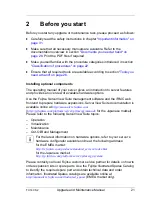
Replacing a defective component
The global error indicators on the front and rear sides of the server as well as
local diagnostic LEDs on the front panel report defective hardware components
that need to be replaced. For further information on the controls and indicators
of your server, refer to the "PRIMERGY TX140 S2 Server Operating Manual"
and section
"Connectors and indicators" on page 320
.
If the system has been powered off in order to replace a non-hot plug unit, a
system of PRIMERGY diagnostic indicators guides you to the defective
component. The "Indicate CSS" button enables the indicator next to the
defective component even if the server has been switched off and disconnected
from the mains. For further information, please refer to sections
"Using
diagnostics information" on page 43
and
"Connectors and indicators on the
front panel" on page 326
.
If the defective component is a customer replaceable unit included in the CSS
concept (Customer Self Service, only available for EMEA market), the CSS
indicators on the front and rear side of the server will light up.
For further information, refer to the "ServerView Suite Local Service Concept
(LSC)" manual available online at
http://manuals.ts.fujitsu.com
(EMEA market) or
http://jp.fujitsu.com/platform/server/primergy/manual/
(Japanese market).
It is recommended to prepare local maintenance tasks using remote diagnostics
procedures, as described in the "ServerView Suite Local Service Concept
(LSC)" manual.
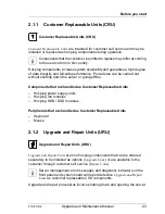
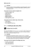
2.1
Classification of procedures
The complexity of maintenance procedures varies significantly. Procedures
have been assigned to one of three unit categories, indicating the level of
difficulty and required qualification.
At the beginning of each procedure, the involved unit type is indicated by one of
the symbols introduced in this section.
I
Please ask your local Fujitsu service center for more detailed
information.
Содержание PRIMERGY TX140 S2
Страница 30: ...30 Upgrade and Maintenance Manual TX140 S2 Before you start ...
Страница 98: ...98 Upgrade and Maintenance Manual TX140 S2 Basic software procedures ...
Страница 120: ...120 Upgrade and Maintenance Manual TX140 S2 Power supply ...
Страница 148: ...148 Upgrade and Maintenance Manual TX140 S2 Hard disk drives solid state drives ...
Страница 158: ...158 Upgrade and Maintenance Manual TX140 S2 System fan and air duct ...
Страница 208: ...208 Upgrade and Maintenance Manual TX140 S2 Expansion cards and backup units ...
Страница 216: ...216 Upgrade and Maintenance Manual TX140 S2 Main memory ...
Страница 314: ...314 Upgrade and Maintenance Manual TX140 S2 Cabling ...
Страница 332: ...332 Upgrade and Maintenance Manual TX140 S2 Appendix ...


