


En-4
4.2. Pipe requirement
CAUTION
Refer to the installation manual for the outdoor unit for description of allowable pipe
length and height difference.
Use pipe with water-resistant heat insulation.
CAUTION
Install heat insulation around both the gas and liquid pipes. Failure to do so may cause
water leaks.
Use heat insulation with heat resistance above 120 °C. (Reverse cycle model only)
In addition, if the humidity level at the installation location of the refrigerant piping is
expected to exceed 70 %, install heat insulation around the refrigerant piping. If the
expected humidity level is 70 to 80 %, use heat insulation that is 15 mm or thicker and
if the expected humidity exceeds 80 %, use heat insulation that is 20 mm or thicker. If
heat insulation is used that is not as thick as specified, condensation may form on the
surface of the insulation. In addition, use heat insulation with heat conductivity of 0.045
W/(m·K) or less (at 20 °C).
4.3. Flare connection (pipe connection)
WARNING
Tighten the flare nuts with a torque wrench using the specified tightening method. Oth-
erwise, the flare nuts could break after a prolonged period, causing refrigerant to leak
and generate hazardous gas if the refrigerant comes into contact with a flame.
4.3.1. Flaring
Use special flare tool exclusive for R410A.
(1) Cut the connection pipe to the necessary length with a pipe cutter.
(2) Hold the pipe downward so that cuttings will not enter the pipe and remove any burrs.
(3) Insert the flare nut (always use the flare nut attached to the indoor and outdoor units (or
RB unit) respectively) onto the pipe and perform the flare processing with a flare tool.
Use the special R410A flare tool. Leakage of refrigerant may result if other flare nuts are
used.
(4) Protect the pipes by pinching them or with tape to prevent dust, dirt, or water from
entering the pipes.
Pipe
A
Die
B
Check if [L] is flared uniformly and
is not cracked or scratched.
Pipe outside diameter
[mm (in)]
Dimension A [mm]
Dimension B
-
0
0.4
[mm]
Flare tool for R410A,
clutch type
6.35 (1/4)
0 to 0.5
9.1
9.52 (3/8)
13.2
12.70 (1/2)
16.6
15.88 (5/8)
19.7
19.05 (3/4)
24.0
When using conventional (R22) flare tools to flare R410A pipes, the dimension A should
be approximately 0.5 mm more than indicated in the table (for flaring with R410A flare
tools) to achieve the specified flaring. Use a thickness gauge to measure the dimension A.
It is recommended that a R410A flaring tool is used.
Width across
flats
Pipe outside diameter
[mm (in)]
Width across flats of
Flare nut [mm]
6.35 (1/4)
17
9.52 (3/8)
22
12.70 (1/2)
26
15.88 (5/8)
29
19.05 (3/4)
36
4.3.2. Bending pipes
• If pipes are shaped by hand, be careful not to collapse them.
• Do not bend the pipes in an angle more than 90°.
•
When pipes are repeatedly bent or stretched, the material will harden, making it difficult
to bend or stretch them anymore.
• Do not bend or stretch the pipes more than 3 times.
CAUTION
To prevent breaking of the pipe, avoid sharp bends.
If the pipe is bent repeatedly at the same place, it will break.
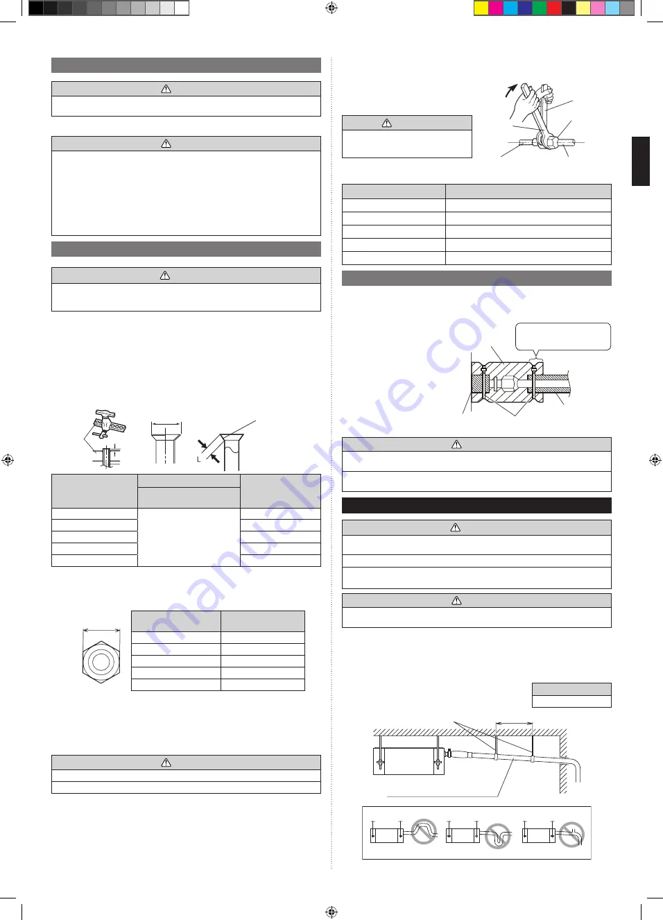
4.3.3. Pipe connection
When the flare nut is tightened properly by
your hand, hold the body side coupling with
a separate spanner, then tighten with a
torque wrench. (See the table below for the
flare nut tightening torques.)
Connection pipe
Flare nut
Tighten with 2
wrenches.
Torque
wrench
Indoor unit pipe
(Body side)
Holding
wrench
CAUTION
Hold the torque wrench at its grip, keep
-
ing it at a right angle with the pipe, in
order to tighten the flare nut correctly.
Flare nut [mm (in)]
Tightening torque [N·m (kgf·cm)]
6.35 (1/4) dia.
16 to 18 (160 to 180)
9.52 (3/8) dia.
32 to 42 (320 to 420)
12.70 (1/2) dia.
49 to 61 (490 to 610)
15.88 (5/8) dia.
63 to 75 (630 to 750)
19.05 (3/4) dia.
90 to 110 (900 to 1,100)
4.4. Installing heat insulation
Install the heat insulation material after performing a refrigerant leak check (see the Instal
-
lation Manual for the outdoor unit for details).
Coupler heat insulation
• Insulate by the coupler heat
insulation (Accessories) around
the gas pipe and liquid pipe of
indoor side.
• After installing the coupler heat
insulation, wrap both end with vi-
nyl tape so that there is no gap.
• After affixing the coupler heat
insulation, secure it with 2 cable
ties (large), one on each end of
the insulation.
•
Make sure that the cable ties
overlap the heat insulation pipe.
Coupler heat
insulation
(Accessories)
Cable tie (Large)
(Accessories)
Heat insulation
Heat insu-
lation
Cover this portion with
heat insulation.
CAUTION
After checking for gas leaks (refer to the Installation Manual of the outdoor unit), per
-
form this section.
Install heat insulation around both the large (gas) and small (liquid) pipes. Failure to do
so may cause water leaks.
5. INSTALLING DRAIN PIPES
WARNING
Do not insert the drain piping into the sewer where sulfurous gas occurs. (Heat ex-
change erosion may occur)
Insulate the parts properly so that water will not drip from the connection parts.
Check for proper drainage after the construction by using the visible portion of transpar
-
ent drain port and the drain piping final outlet on the body.
CAUTION
Do not apply adhesive agent on the drain port of the body. (Use the attached drain hose
and connect the drain piping)
• Install the drain pipe with downward gradient (1/100 to 1/50) and so there are no rises or
traps in the pipe. Unsmooth draining caused by accumulated water flow in the pipe may
cause clogged drain.
• Use general hard polyvinyl chloride pipe (VP25) [outside diameter 32 mm].
• When the pipe is long, install supporters.
• Do not perform air bleeding. Drainage may be blown out.
• Always heat insulate the indoor side of the drain pipe.
• If it is impossible to have sufficient gradient of pipe, perform
drain lift-up.
Drain pipe size
VP25 (O.D. 32 mm)
Hanging fittings
VP25 (O.D. 32 mm)
Downward gradient 1/100 to 1/50
1.5 to 2 m
Rise
PROHIBITED:
Trap
Air bleeding
9371022635-01_IM.indb 4
08/02/2019 17:03:10


