background image

22

4.  SETUP AND MAINTENANCE

4

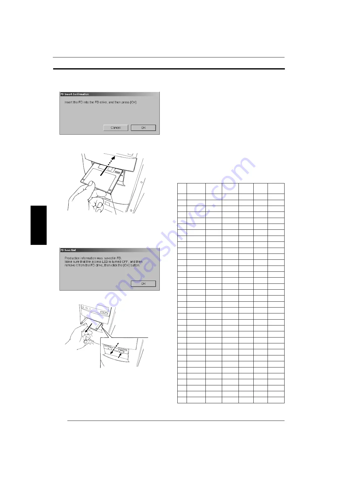
1) Click the [FD Save] button.

2) Insert the formatted floppy disk into the floppy drive of the 

main control unit.

Z

2

041

3) Click the [OK] button.

• The data is saved into the floppy disk.

4) Remove the floppy disk from the floppy disk drive.

Z

2

042

5) Click the [OK] button.

• The dialog box disappears.

3. Click the [OK] button.

• Operation returns to the menu screen.

4.3

Print Condition Setup and Check

4.3.1 Paper Condition Setup (0200)

See the “Operating Instructions” manual.

4.3.2 Print Size Setup (0220)

[Selection]

[Setup and Maintenance] 

 [02 Print Condition Setup and 

Check] 

 [0220 Print Size Setup]

[Procedure]

Set the print size to be used.

• Normally, the size is registered as shown in the following 

table.

Floppy Disk

No.

Print Size

Width

[0.1mm]

Length

[0.1mm]

Display

Border

Simple 
Setting

1

89C

89.0

127.0

ON

BL

1

2

89P

89.0

254.0

ON

BL

3

89H

89.0

158.0

ON

BL

4

102C

102.0

152.0

ON

BL

2

5

102P

102.0

254.0

ON

BL

6

102H

102.0

178.0

ON

BL

7

3R

127.0

89.0

ON

BL

3

8

3RBD

127.0

89.0

OFF

BD

9

5R

127.0

178.0

ON

BL

10

5RBD

127.0

178.0

OFF

BD

11

4R

152.0

102.0

ON

BL

4

12

4RBD

152.0

102.0

OFF

BD

13

6R

152.0

203.0

ON

BL

14

6RW

152.0

216.0

OFF

BL

15

8R

203.0

254.0

ON

BL

5

16

8RW

203.0

305.0

OFF

BL

17

A5

210.0

148.0

OFF

BL

18

A4

210.0

297.0

ON

BL

19

8R1

254.0

203.0

OFF

BL

20

10R

254.0

305.0

OFF

BL

21

10RW

254.0

381.0

OFF

BL

22

11

×

14

279.0

356.0

OFF

BL

23

11

×

17

279.0

432.0

OFF

BL

24

12

×

10

305.0

254.0

OFF

BL

25

12

×

15

305.0

381.0

ON

BL

26

12

×

18

305.0

457.0

OFF

BL

27

3DSC

89.0

119.0

OFF

BL

28

3DSCf

89.0

127.0

OFF

BD

29

4DSC

102.0

136.0

OFF

BL

30

4DSCf

102.0

152.0

OFF

BD

31

5DSC

127.0

169.0

OFF

BL

32

5DSCf

127.0

178.0

OFF

BD

33

89lx

89.0

120.0

OFF

BL

34

CDIDX

102.0

120.0

OFF

BL

35

127lx

127.0

120.0

OFF

BL

4.3

4.3.1

4.3.2

SP3000_instruct_E.book 22 ページ 2007年12月11日 火曜日 午後1時6分

Содержание SP-3000

Страница 1: ...Second Edition INSTRUCTION MANUAL FRONTIER WORKFLOW MANAGEMENT SOFTWARE FILM SCANNER CONNECTION SOFTWARE FOR SP 3000 Condition Setup and Maintenance PP3 B1271E2 MS11 Ver 1 0...

Страница 2: ...NOTE This equipment has been tested and found to comply with the limits for a Class A digital device pursuant to Part 15 of the FCC Rules These limits are designed to provide reasonable protection ag...

Страница 3: ...Y AND USE CONDITIONS 2 COMPONENTS AND RELATED FUNCTIONS 3 MENU TABLE 4 SETUP AND MAINTENANCE 5 SPECIAL PRINTING FUNCTIONS AND USE OF MAINTENANCE MENU 6 MAIN SPECIFICATIONS 7 INDEX 1 2 3 4 5 6 7 SP3000...

Страница 4: ...oduction Information 0120 18 4 2 3 Data Backup 0122 20 4 2 4 Equipment Name Set 0124 20 4 2 5 Timer Waiting Time Setup 0125 21 4 2 6 Installation Information Reference 0126 21 4 2 7 Accumulated Produc...

Страница 5: ...io Setup Menu 0426 41 5 1 2 Focus Position Adjustment Menu 0321 41 5 1 3 Mask Position Adjustment Menu 0420 42 5 2 How to Print Underexposed Film and Fixed Feeding Adjustment 43 5 2 1 Fixed Feed Selec...

Страница 6: ...y 1 1 1 Basic Operating Precautions When accessing the machine interior for inspection or servicing shut down the system by doing the post operational checks place the built in circuit breaker in the...

Страница 7: ...achine if the surrounding floor is wet Ensure the electrical earth connection is permanently made Ensure that all cables are undamaged and correctly connected x Do not place items such as a cup plasti...

Страница 8: ...auto film carrier correctly observe the following precautions Precautions for installing film or cartridge into the auto film carrier NC100AY z The following operations must be performed slowly and s...

Страница 9: ...with the alcohol water during the post operational check If the magnetic heads are dirty a magnetic information reading failure may result Do not use a film cleaner or alcohol water when cleaning the...

Страница 10: ...If the middle of a film is fogged or a frame is greatly overexposed the NC100AY cannot be used Use the MFC10AY optional when scanning such film If the leading or trailing end of a film is overexposed...

Страница 11: ...11 1 1 OPERATIONAL SAFETY AND USE CONDITIONS 1 3 Certification and Identification Labels 1 3 1 Certification and Identification Label Locations FF TPO 1 3 1 3 1 SP3000_instruct_E book 11...

Страница 12: ...lm Carrier NC100AY Film Carrier Lock Release Lever Film Receiver Built in Circuit Breaker START Switch Power Supply Unit Image Processing Box Main Control Unit Full Keyboard Operation Keyboard Film Re...

Страница 13: ...i film carrier MFC10AY and auto film carrier NC120AY 4 Diffusion Box 110 to 135 120 replacement type 5 LED Light Source Unit LED circuit board with R 64 G 40 B 50 and IR 144 Scanner Section Cooling Fa...

Страница 14: ...14 2 COMPONENTS AND RELATED FUNCTIONS 2 2 3 Keyboard Functions Full Keyboard Z2451 Operation Keyboard EZ622 Pressure Release 2 3 SP3000_instruct_E book 14...

Страница 15: ...ow Cancels the color corrections specified by the color keys Specifies multiple printing Press this key and enter number of prints with numeral keys Feeds the image to the left at low speed Feeds the...

Страница 16: ...rection Setting K 4 3 5 0225 Custom Setting Regist Delete K 4 3 6 03 Scanner Adjustment Maintenance 0300 Image Scanning Method K K 4 4 1 0320 Input Check K 4 4 2 0321 Focus Position Adjustment K 4 4 3...

Страница 17: ...0 in the Password box 4 Click the OK button The submenu screen appears 5 Click the button in the submenu in the left hand box The menu items appear in the right hand box 6 Click the desired item butto...

Страница 18: ...ings 0101 See the Operating Instructions manual 4 2 2 Production Information 0120 Selection Setup and Maintenance 01 System Operation Setup and Check 0120 Production Information Procedure Confirm the...

Страница 19: ...he floppy disk drive Z2042 5 Click the OK button The dialog box disappears 3 To clear the data follow these steps 1 In Input Type choose which data you wish to clear 2 Then click the Clear button The...

Страница 20: ...printer processor data 2 Move the cursor to the Destination box and select Film Scanner or Printer processor 3 Click the OK button Making the backup of the data message appears 4 Insert the floppy dis...

Страница 21: ...effects at Auto film feed mode only Waiting time for the pos adjust of the 1st frame Set up the display time of the black white image appears in the view and order screen 1 Move the cursor to the time...

Страница 22: ...ple Setting 1 89C 89 0 127 0 ON BL 1 2 89P 89 0 254 0 ON BL 3 89H 89 0 158 0 ON BL 4 102C 102 0 152 0 ON BL 2 5 102P 102 0 254 0 ON BL 6 102H 102 0 178 0 ON BL 7 3R 127 0 89 0 ON BL 3 8 3RBD 127 0 89...

Страница 23: ...isplay 4 Click the OK button Operation returns to the menu screen 4 3 3 Monitor Adjustment 0222 Selection Setup and Maintenance 02 Print Condition Setup and Check 0222 Monitor Adjustment Procedure Set...

Страница 24: ...ial monotone film Also fine adjust the slope for color and balance for black white DX Code and Film Name Registration 1 Pre scan the film to be registered on the view and order screen 2 Click the i bu...

Страница 25: ...g 1 Select the channel number to be deleted in the CH No box The DX code and name are displayed in the Registered DX Code box 2 Click the Delete button The DX code is deleted 3 Click the OK button Ope...

Страница 26: ...using the full keyboard 4 Click the Cond Edit button The Initial Value Selection dialog box appears 5 Select the number to be used as the initial value 6 Click the OK button Input Type Negative The 1...

Страница 27: ...ain Control Process Sharpness Large size Setup and Minimizing Color Spreading Sharpness Sharpness Level Low 3 Low 2 Low 1 Normal High 1 High 2 High 3 Under Level 2 1 0 Sharpness can only be set indivi...

Страница 28: ...0 1 2 Input Type Reversal The 1 Corr Level Tone Hypertone panel appears 1 Set up the Correct Level and Tone Adjustment Correct Level Tone Adjustment Standard All Hard All Soft Highlight Hard Highligh...

Страница 29: ...r Spreading Sharpness Sharpness Level Low 3 Low 2 Low 1 Normal High 1 High 2 High 3 Grain Control Process Sharpness Large size Setup Sharpness can be set up individually for magnification entered in t...

Страница 30: ...y Step Width BL SL panel appears 3 Set up the key step width and balance slope NOTE Click the Default to return the key step width setup to the initial value Key Step Width Setup Dc Dm Dy Normally ent...

Страница 31: ...ct number to be deleted and click the Delete button 9 Click the OK button Operation returns to the menu screen 4 4 Scanner Adjustment Maintenance 4 4 1 Image Scanning Method 0300 See the Operating Ins...

Страница 32: ...ask type 5 Except for mount mask Insert a film into the carrier or mask NOTE For the NC100AY use a film having more than five frames For the NC120AY use a film having more than 200 mm in length 6 Clic...

Страница 33: ...e Carrier box For NC100AY 1 Select Carrier Setting or Each Film for AF Timing of One way Mode Carrier Setting Auto focusing is executed when the NC100AY is installed or the feed lane is changed from t...

Страница 34: ...tialize button to return initial setting 4 Click the Page 3 tab 5 Select Each Frame or Per 1 order for AF Timing of AC Each Frame Auto focusing is executed for each frame Per 1 order Auto focusing is...

Страница 35: ...n 4 Click the Close button Operation returns to the menu screen 4 5 Carrier Adjustment Maintenance 4 5 1 NC100AY Fixed Feeding Setup 0400 See the Operating Instructions manual 4 5 2 Mask Position Adju...

Страница 36: ...status of each sensor of the auto film carrier NC100AY can be checked Install the auto film carrier NC100AY before performing the steps on this menu Selection Setup and Maintenance 04 Carrier Adjustme...

Страница 37: ...stall the auto film carrier NC100AY 2 Click the Next button 3 Click the Next button 4 Click the Close button Operation returns to the menu screen 4 5 6 MFC10AY Working Information Display 0424 Selecti...

Страница 38: ...dure Set up the monitor frame ratio for each mask 1 Select the carrier ID to be set up 2 Change the monitor frame ratio NOTE Set the monitor frame ratio to 95 normally If more than 95 is set up the fi...

Страница 39: ...e set up 2 Change the monitor frame ratio NOTE Set the monitor frame ratio to 95 for 135F H P mount IX240 mount and 110 and 98 for the other films If values greater than these are set up the film mask...

Страница 40: ...0720 Image Processing Section Information Display Procedure Check the displayed DIMM PCI slot mounting status mounted or unmounted in image processing box as well as each processing capacity circuit...

Страница 41: ...er films 4 Click the Storage button The changed data is saved 5 Click the OK button 6 Click the Close button Operation returns the menu screen 5 1 2 Focus Position Adjustment Menu 0321 1 Click the Set...

Страница 42: ...her carriers or masks to be registered 10 Click the Close button Operation returns to the menu screen 5 1 3 Mask Position Adjustment Menu 0420 NOTE To adjust the mask position for the 135 reversal mou...

Страница 43: ...eed when printing an underexposed 135 film If the film feed length is incorrect adjust it in Menu 0400 5 2 1 Fixed Feed Selection and Feed Length Check 1 Click the Operational Environment Settings but...

Страница 44: ...Regist button 4 Check the feed length by repeating the steps given in Subsection 5 2 1 5 3 Special Printing Functions 5 3 1 Changing Finished Image To change the finished image for a specific film set...

Страница 45: ...t Match Prints If color balance of the monitor does not match prints perform Menu 0222 Monitor Adjustment see Subsection 4 3 3 5 3 5 Frequent Occurrence of Auto Focusing Error When errors concerning a...

Страница 46: ...olor reproduction processing gradation control facial expression enhancement hyper tone processing hyper sharpness processing monotone finishing retouching function dust or scratches on film can be er...

Страница 47: ...k Position Adjustment 0420 4 5 2 Mask Position Adjustment Menu 0420 5 1 3 MENU TABLE 3 MFC10AY Input Check 0422 4 5 4 MFC10AY Monitor Frame Ratio Setup 0426 4 5 8 MFC10AY Monitor Frame Ratio Setup Men...

Страница 48: ...04604 901 Brazil in Asia FUJIFILM SINGAPORE PTE LTD 10 New Industrial Road Fujifilm Building Singapore 536201 FUJIFILM THAILAND LTD S P Building 8th Floor 388 Phaholyothin Road Bangkok 10400 Thailand...

Отзывы: