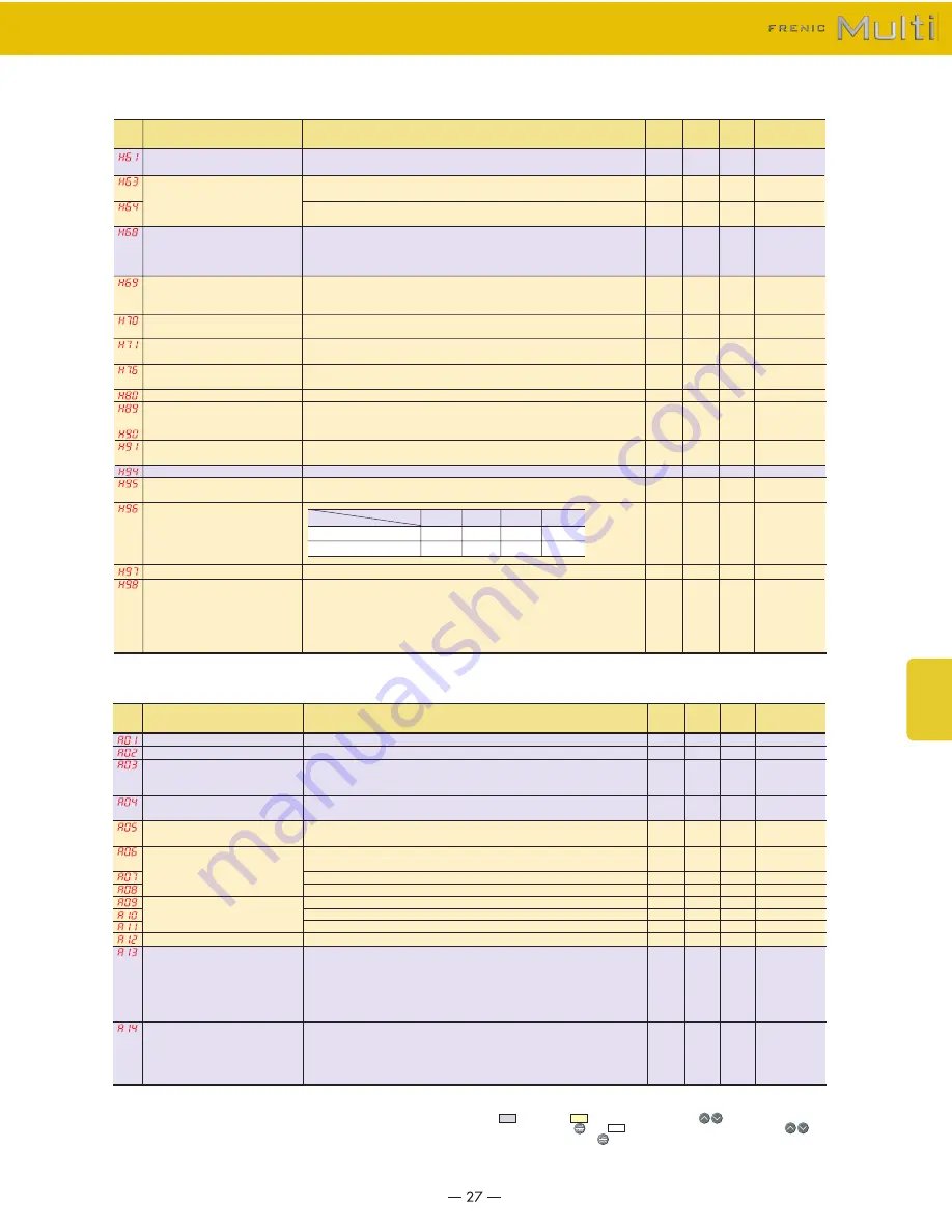
FujiFilm FRN001E1E-2U Скачать руководство пользователя страница 27

UP/DOWN Control

Low Limiter

Slip Compensation 1

Automatic Deceleration

Overload Prevention Control

Deceleration Characteristics

Torque Limiter
(Frequency increment limit for braking)
Output Current Fluctuation Damping Gain for Motor 1
Reserved. 

*3

C1 Disconnection Detection Time 
(PID control feedback line)
Cumulative Motor Run Time 1
DC Braking

STOP Key Priority/
Start Check Function

Clear Alarm Data
Protection/Maintenance Function

  0 : 0.00
  1 : Last UP /DOWN command value on releasing run command
  0 : Limit by F16 (Frequency limiter: Low) and continue to run
  1 : If the output frequency lowers less than the one limited by F16 (Frequency limiter: Low), decelerate to stop the motor.
0.0 (Depends on F16 (Frequency limiter: Low)) 
0.1 to 60.0
  0 : Enable during ACC/DEC and enable at base frequency or above
  1 : Disable during ACC/DEC and enable at base frequency or above
  2 : Enable during ACC/DEC and disable at base frequency or above
  3 : Disable during ACC/DEC and disable at base frequency or above
  0 : Disable
  2 : Enable (Canceled if actual deceleration time exceeds three times the one specified by F08/E11.)
  4 : Enable (Not canceled if actual deceleration time exceeds three times the one specified by F08/E11.)
0.00 :  Follow deceleration time specified by F08/E11 0.01 to 100.0 
999: Disable
  0 : Disable
  1 : Enable
0.0 to 400.0

0.00 to 0.40

0.0: Disable
0.1 to 60.0: Detection time
Change or reset the cumulative data
0 : Slow
1 : Quick


Setting H97 data to "1" clears alarm data and then returns to zero.
0 to 31: Display data on the keypad's LED monitor in decimal format (In each bit, "0" for disabled, "1" for enabled.) 
Bit 0 : Lower the carrier frequency automatically 
Bit 1 : Detect input phase loss 
Bit 2 : Detect output phase loss 
Bit 3 : Select life judgment threshold of DC link bus capacitor 
Bit 4 : Judge the life of DC link bus capacitor

-

-

0.1

-

-

0.01

-

0.1

0.01

-

-
-

-

-
-

-

-

Hz

-

-

Hz/s

-

Hz

-

-

-
-

-

-
-

1

0

1.6

0

0

999

0

5.0

0.20

0.0

-

1

0

0

19

(bit 4,1,0=1)

25.0 to 400.0
25.0 to 400.0
0: Output a voltage in proportion to input voltage
80 to 240: Output an AVR-controlled voltage (for 230 V class series) 
160 to 500: Output an AVR-controlled voltage (for 460 V class series)
80 to 240V: Output an AVR-controlled voltage (for 230 V class series) 
160 to 500V: Output an AVR-controlled voltage (for 460 V class series)
0.0 to 20.0(percentage with respect to "A03: Rated Voltage at Base Frequency 2") 
Note: This setting takes effect when A13 = 0, 1, 3, or 4.
  1 : For a general-purpose motor with shaft-driven cooling fan
  2 : For an inverter-driven motor, non-ventilated motor, or motor with separately powered cooling fan
0.00 : Disable 1 to 135% of the rated current (allowable continuous drive current) of the motor
0.5 to 75.0
0.0 to 60.0 Hz
0 to 100
0.00 : Disable 0.01 to 30.00
0.1 to 60.0
0 : Variable torque load
1 : Constant torque load
2 : Auto-torque boost
3 : Auto-energy saving operation (Variable torque load during ACC/DEC)
4 : Auto-energy saving operation (Constant torque load during ACC/DEC)
5 : Auto-energy saving operation (Auto-torque boost during ACC/DEC)
0 : V/f operation with slip compensation inactive
1 : Dynamic torque vector operation
2 : V/f operation with slip compensation active
3 : V/f operation with PG
4 : Dynamic torque vector operation with PG

0.1
0.1

1

1

0.1

-

0.01

0.1
0.1

1

0.01

0.1

-

-

Hz
Hz

V

V

%

-

A

min

Hz

%

s

Hz

-

-

Y
Y

Y2

Y2

Y

Y

Y1Y2

Y
Y
Y
Y
Y
Y

Y

60.0
60.0

230
460
230
460

Depending on 

the inverter capacity

1

100% of the motor rated current

5.0
0.0

0

0.00

0.5

1

0

 (Initial frequency setting) 

(Mode selection)

(Lower limiting frequency)

(Operating conditions)

(Mode selection)

(Braking response mode)

(Mode selection)

Y

Y

Y

Y

Y

Y

Y

Y

Y

N
Y

Y

N
Y

STOP key priority

Start check function

Item

Data

0

Disable

Disable

1

Enable

Disable

2

Disable

Enable

3

Enable

Enable

Maximum Frequency 2
Base Frequency 2
Rated Voltage at Base 
Frequency 2

Maximum output Voltage 2

Torque Boost 2

Electronic Thermal Overload Protection for Motor 2

DC 
Braking 2

Starting Frequency 2
Load Selection/
Auto Torque Boost /
Auto Energy Saving Operation 2

Control Mode Selection 2

(Select motor characteristics)

(Overload detection level)

(Thermal time constant)

(Braking starting frequency)

(Braking level)

(Braking time)

*3 Reserved for the maker. Do not set any data.
<Changing, validating, and saving function code data when the motor is running>
        : Impossible,          : Possible (Change data with           keys and then 
save/validate it with      key),         : Possible (Change and validate data with           
keys and then save it with      key)

A codes: Motor 2 Parameters

H codes: High Performance Functions

Func.

Code

Data 

copy

*2

Name

Data setting range

Default setting

Min.

Unit

Func.

Code

Data 

copy

*2

Name

Data setting range

Default setting

Min.

Unit

*1 When you make settings from the keypad, the incremental unit is restricted by the number of 

digits that the LED monitor can display.


(Example) If the setting range is from -200.00 to 200.00, the incremental unit is as follows:


"1" for -200 to -100, "0.1" for -99.9 to -10.0, "0.01" for -9.99 to -0.01, "0.01" for 0.00 to 99.99, 
and "0.1" for 100.0 to 200.0

*2 Symbols in the "Data copy" column
 

Y: Will be copied unconditionally.


Y1: Will not be copied if the rated capacity differs from the source inverter.


Y2: Will not be copied if the rated input voltage differs from the source inverter.

N: Will not be copied.

~

Functions

Settings

Содержание FRN001E1E-2U

Страница 1: ...MEH531 High Performance Compact Inverters...

Страница 2: ...kes it possible to reduce the effect on peripheral equipment The design life of each internal component with limited life has been extended to 10 years This helps to extend the maintenance cycle for y...

Страница 3: ...dhorizontalconveyance Impacts are detected mechanically and not only can the inverter s operation pattern be set on coast to stop or deceleration stop but switching from torque limitation to current l...

Страница 4: ...oequipmentmaintenanceisdisplayed Detailed information can be checked for the four most recent alarms The alarm history records the latest four incidents Item Purpose Motor cumulative running time hr N...

Страница 5: ...direction and operation of the fan is picked up to start the fan smoothly This function is convenient in such cases as when switching instantaneously from commercial power supply to the inverter Equip...

Страница 6: ...or and have two communications ports Complies with standards Sink Source switchable Wide voltage range The multi function keypad displays multiple languages Japanese English German French Spanish Ital...

Страница 7: ...4U FRN015E1E 4U FRN020E1E 4U Semi standard type EMC filter built in type FRNF12E1E 7U FRNF25E1E 7U FRNF50E1E 7U FRN001E1E 7U FRN002E1E 7U FRN003E1E 7U Three phase 230V Three phase 460V Single phase 23...

Страница 8: ...ated current 150 Built in Three phase 230V 1 8 to 20HP Three phase 460V 1 2 to 20HP Standard type 1 Fuji s 4 pole standard motor 2 Rated capacity is calculated by assuming the output rated voltage as...

Страница 9: ...oling method EMC standard Emission compliance Immunity Weight Mass lbs kg Rated capacity kVA 2 Rated voltage V 3 Rated current A 4 Overload capability Rated frequency Hz Phases voltage frequency Volta...

Страница 10: ...is set the time setting is cancelled and acceleration and deceleration is made according to the pattern given with an external signal Acceleration and deceleration time can be independently set with...

Страница 11: ...e number of pulses to the stop position and deceleration point Select either of reverse prevention or forward rotation prevention The life early warning of the main circuit capacitors capacitors on th...

Страница 12: ...6 5 0 28 7 0 26 6 5 W D D1 D2 C elongated hole 0 2 5 0 24 6 H1 0 24 6 H C Name plate W1 0 24 6 0 24 6 W H1 0 24 6 0 24 6 H 0 2 5 0 2 5 D2 D1 D C Name plate W1 0 31 8 0 31 8 W H1 0 31 8 0 28 7 H 2 R0 1...

Страница 13: ...6 3 82 97 3 82 97 5 04 128 6 46 164 7 72 196 2 64 67 3 82 97 5 04 128 4 72 120 5 12 130 7 09 180 8 66 220 10 24 260 5 12 130 5 12 130 7 09 180 8 66 220 10 24 260 4 72 120 5 12 130 7 09 180 4 33 110 4...

Страница 14: ...97 0 26 6 5 0 26 6 5 W D D1 D2 H H1 4 65 118 0 24 6 0 24 6 3 5 89 D3 0 41 10 5 4 0 2 06 4 5x7 elongated hole 0 36 92 0 2 5 D3 1 06 27 0 41 10 5 W 6 61 168 H H1 7 48 190 5 04 128 0 24 6 0 24 6 0 24 6...

Страница 15: ...4 33 110 5 51 140 7 15 181 5 8 66 220 3 15 80 4 33 110 5 51 140 4 72 120 7 09 180 11 22 285 13 78 357 5 12 130 7 09 180 11 22 285 13 07 332 4 72 120 5 12 130 7 09 180 6 69 170 9 65 245 7 09 180 9 65 2...

Страница 16: ...urs during operation the lamp is unlit during keypad operation and lit during terminal block operation LED monitor When the motor is running or stopped The monitor displays speeds such as output frequ...

Страница 17: ...when installing a coil such as the MC or solenoid near the inverter Note4 THR function can be used by assigning code 9 external alarm to any of the terminals X1 to X5 FWD or REV function code E01 to...

Страница 18: ...and the motor coasts to stop ON across Hz2 Hz1 and CM Freq set 2 is effective ON across M2 M1 and CM The motor 2 setting is available OFF across M2 M1 and CM The motor 1 setting is available ON across...

Страница 19: ...for PC loader Analog monitor Pulse monitor Transistor output power Transistor output 1 Transistor output 2 Inverter running Inverter output on Speed freq arrival Speed freq detection Undervoltage dete...

Страница 20: ...FRN007E1 4U FRN010E1 4U FRN015E1 4U FRN020E1 4U FRNF12E1 7U FRNF25E1 7U FRNF50E1 7U FRN001E1 7U FRN002E1 7U FRN003E1 7U Fig A Fig B Fig B Fig C Fig C Fig D Fig E Three phase 230V Single phase 230V Thr...

Страница 21: ...r connection between the control board and power source board or interface board or short circuit between terminals between 13 and 11 is detected Simulated alarm is output to check the fault sequence...

Страница 22: ...tput frequency 2 after slip compensation 2 Output current 3 Output voltage 4 Output torque 5 Load factor 6 Input power 7 PID feedback amount PV 8 PG feedback value 9 DC link bus voltage 10 Universal A...

Страница 23: ...Y2 and 30A B C as listed below 0 1000 Inverter running RUN 1 1001 Frequency arrival signal FAR 2 1002 Frequency detected FDT 3 1003 Undervoltage detected Inverter stopped LU 4 1004 Torque polarity de...

Страница 24: ...mode Menus 0 and 1 1 Function code data check mode Menu 2 2 Full menu mode Menus 0 through 6 0 Current input C1 function 4 to 20 mADC 1 Voltage input V2 function 0 to 10 VDC Selecting function code d...

Страница 25: ...0 0 00 0 00 0 00 0 00 0 00 0 00 0 2 0 0 100 0 0 05 100 0 1 0 0 100 0 0 05 100 0 0 0 100 0 0 05 100 0 0 00 0 00 0 00 0 Hysteresis width offset Gain Filter time constant Gain base point Polarity offset...

Страница 26: ...0 Disable Always in operation 1 Enable ON OFF controllable 0 Linear 1 S curve Weak 2 S curve Strong 3 Curvilinear 0 Disable 1 Enable Reverse rotation inhibited 2 Enable Forward rotation inhibited 0 Di...

Страница 27: ...motor with separately powered cooling fan 0 00 Disable 1 to 135 of the rated current allowable continuous drive current of the motor 0 5 to 75 0 0 0 to 60 0 Hz 0 to 100 0 00 Disable 0 01 to 30 00 0 1...

Страница 28: ...Y Y Y Y Y Y Y Y Y Y Y Y Y Y Y Y Y Y Y Y Y Y Y Y Y Y Y Y 0 0 0 100 0 0 0 00 0 5 200 0 100 0 999 999 0 10 0 0 0 100 0 0 0 00 0 0 100 0 0 0 100 1 0 1 0 1 0 1 0 Pole kW HP A A s Hz 2 0 01 0 01 0 01 0 01...

Страница 29: ...5 link Loader Follow H30 and y98 data 2 Follow H30 and y98 data Via RS 485 link Loader 3 Via RS 485 link Loader Via RS 485 link Loader 1 0 1 1 0 01 1 0 1 1 0 01 s s s s s s Y Y Y Y Y Y Y Y Y Y Y Y Y Y...

Страница 30: ...4 Writing function code allocation 5 Writing function code allocation 6 Writing function code allocation 7 Writing function code allocation 8 Read function code allocation 1 Read function code alloca...

Страница 31: ...g reactor is not used in the thyristors transformer it is necessary to connect an AC reactor on the inverter s input side and so be sure to verify that this is done 3 Used to prevent tripping in cases...

Страница 32: ...55 140 55 37 55 75 50 55 140 55 38 55 75 50 55 45 30 20 20 10 45 30 20 20 10 45 30 250 133 73 50 75 20 10 250 133 73 50 75 20 10 250 133 73 50 0 06 0 044 0 09 0 068 0 10 0 075 0 10 0 077 0 12 0 093 0...

Страница 33: ...1 5 2x8 0 20x0 31 5 2x8 0 20x0 31 5 2x8 0 24x0 43 6x11 0 24x0 43 6x11 0 24x0 43 6x11 0 28x0 43 7x11 0 28x0 43 7x11 0 28x0 43 7x11 0 20x0 31 5 2x8 0 20x0 31 5 2x8 0 20x0 31 5 2x8 0 24x0 35 6x9 0 24x0 3...

Страница 34: ...generator PG RS 485 communication card OPC F1 RS Connection with a host master device such as PC or PLC allows you to control FRENIC Multi as a subordinate slave device The card is added to the RS 485...

Страница 35: ...the cooling effect and to make the panel more compact 0 44 11 3 0 31 7 8 29 5 75 5 04 128 7 09 180 0 28 7 6 69 170 Optional type Applicable inverter type Previous inverter type FRNF12E1S 2U FRNF25E1S...

Страница 36: ...verter type With DCR Without DCR With DCR Without DCR With DCR Without DCR Output circuit MCCB GFCI rated current A Magnetic contactor MC Input circuit Inverter output U V W DC Reactor P1 P DC Reactor...

Страница 37: ...is difficult to provide repairs or supply spare parts even within this 7 year period For details please confirm at our company s business office or our service office 3 Repair Period after Production...

Страница 38: ...MEMO...

Страница 39: ...MEMO...

Страница 40: ...g a magnetic contactor MC in the output secondary circuit If a magnetic contactor MC is mounted in the inverter s secondary circuit for switching the motor to commercial power or for any other purpose...

Отзывы: