


●
Common specifications
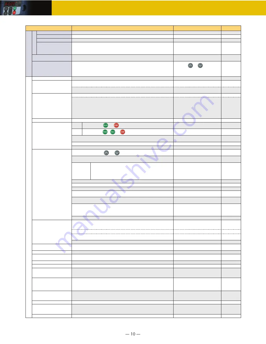
Maximum frequency
Base frequency
Starting frequency
Carrier frequency
Item
Explanation
Related
function code
Remarks
25 to 400Hz variable setting
25 to 400Hz variable setting
0.1 to 60.0Hz variable setting, Duration: 0.0 to 10.0s
•
Analog setting:
±
0.2% of maximum frequency (at 25
±
10
˚
C(at 77
±
50
˚
F))
•
Keypad setting:
±
0.01% of maximum frequency (at -10 to +50
˚
C(at 14 to +
122
˚
F))
•
V/f control
•
Dynamic torque-vector control (magnetic flux estimator)
•
V/f control (with sensor, when the PG interface card (option) is installed)
2 points (Desired voltage and frequency can be set.)
Torque boost can be set with the function code F09.
Set when 0, 1, 3, or 4 is selected at F37.
200% or over (Auto torque boost in 0.5Hz operation, slip compensation and auto torque boost)
Select application load type with the function code F37.
0: Squared variable torque load
1: Constant torque load
2: Auto torque boost
3: Auto energy-save operation (variable torque load in deceleration)
4: Auto energy-save operation (constant torque load)
5: Auto energy-save operation (auto torque boost)
0.75 to 15kHz variable setting
Frequency may drop automatically to protect the
inverter depending on environmental
temperature and output current.This protective
operation can be canceled by function code H98.
Setting with and keys
•
Analog setting: 1/3000 of maximum frequency (ex. 0.02Hz at 60Hz, 0.4Hz at 120Hz)
•
Keypad setting: 0.01Hz (99.99Hz or less), 0.1Hz (100.0Hz or more)
•
Link setting: Selectable from 2 types
•
1/2000 of maximum frequency (ex. 0.003Hz at 60Hz, 0.006Hz at 120Hz)
•
0.01Hz (fixed)
Possible to set output voltage at base frequency and at maximum output frequency (common spec).
AVR control can be turned ON or OFF (Factory setting: OFF).
Three-phase 230V, single-phase 230V: 80 to 240V
Three-phase 460V: 160 to 500V
Three-phase and single-phase 230V: 0 to 240V/0 to 400Hz
Three-phase 400V: 0 to 500V/0 to 400Hz
Keypad
operation
Key operation: Can be set with and keys
Start and stop with and keys
Start and stop with / and keys
External signals (7digital inputs): FWD (REV), RUN, STOP commands (3 wire operation possible),
coast-to-stop, external alarm, alarm reset, etc.
Linked operation: Operation through RS-485 or field buss (option) communications
Switching operation command: Link switching, switching between communication and inverter (keypad or external signals)
Keypad (standard)
Multi-function keypad
With data protection
Connected to analog input terminals 13, 12,
and 11. Potentiometer must be provided.
Multistep frequency: Selectable from 16 steps (step 0 to 15)
UP/DOWN operation: Frequency can be increased or decreased while the digital input signal is ON.
Linked operation: Frequency can be set through RS-485 or field buss (optional) communications.
Switching frequency setting: Frequency setting can be switched (2 settings) with external signal (digital input).
Switching to frequency setting via communication and multi-frequency setting are available.
Auxiliary frequency setting: Terminal 12 input and terminal C1 input (terminal V2 input) can be added
to main setting as auxiliary frequency.
Inverse operation: Normal/inverse operation can be set or switched with digital input signal and
function code setting.
•
+10 to 0V DC /0 to 100% (terminal 12, C1 (V2))
•
+20 to +4mA DC/0 to 100% (terminal C1)
0.00 to 3600s
*If 0.00s is set, the time setting is cancelled and acceleration and deceleration is made
according to the pattern given with an external signal.
Acceleration and deceleration time can be independently set with 2 types and selected with digital input signal (1 point).
Acceleration and deceleration pattern can be selected from 4 types:
Linear, S-curve (weak), S-curve (strong), Non-linear
Deceleration with coasting can be stopped with operation stop command.
Pulse train input: 30kHz (max.)/ Maximum output frequency
When the PG interface card (optional) is installed.
If the set frequency is lower than lower limit, continuous
motor running or stop running motor can be selected.
External volume: Can be set with external potentiometer (1 to 5k
Ω
1/2W)
Analog input
Analog input can be set with external voltage/current input
•
0 to
±
10V DC (0 to
±
5V DC)/0 to
±
100% (terminal 12, C1 (V2))
•
+4 to +20mA DC/0 to 100% (terminal C1)
Accuracy (Stability)
Setting resolution
Control method
Voltage/freq. characteristic
Torque boost
Starting torque
Start/stop
Frequency setting
Acceleration/deceleration time
Frequency limiter
(Upper limit and lower limit frequencies)
Bias
Gain
Jump frequency
(Non-linear V/f setting)
(Load selection)
(Curve)
High and Low limiters can be set. (Setting range: 0 to 400Hz)
Bias of set frequency and PID command can be independently set (setting range: 0 to
±
100%).
Analog input gain can be set between 0 and 200%.
Three operation points and their common jump width (0 to 30.0Hz) can be set.
Timer operation
The inverter operates and stops for the time set with the keypad (1-cycle operation).
Jogging operation
Auto-restart after momentary
power failure
Current limit
Slip compensation
•
Can be operated using digital input signal or keypad.
•
Acceleration and deceleration time (same duration used only for jogging) can be set.
•
Jogging frequency: 0.00 to 400.0Hz
•
Restarts the inverter without stopping the motor after instantaneous power failure.
•
Select "Continuous motor mode" to wait for the power recovering with low output frequency.
•
Restart at 0Hz, restart from the frequency used before momentary power failure, restart at the set frequency can be selected.
•
Motor speed at restart can be searched and restarted.
Voltage signal from terminal 12, C1 (V2) and current
signal (from terminal C1) can be set independently.
F03
F04
F23,F24
F03 to F06
H50 to H53
F09, F37
F09, F37
H68, F37
F02
F02
E01 to E05
E98, E99
H30, y98
F01, C30
F18, C50,
C32 to C34,
C37 to C39,
C42 to C44
C05 to C19
F01, C30
H30, y98
F01, C30
E61 to E63
C53
F07, F08
E10,E11
H07
H11
F15, F16
H63
F18, C50 to C52
C32, C34, C37
C39, C42, C44
C01 to C04
C21
H54
C20
F14
H13 to H16
H92, H93
F26
F27
H98
Keeps the current under the preset value during operation.
Torque limit
•
Controls the output torque lower than the set limit value.
•
Can be switched to the second torque limit with digital input signal.
•
Soft start (filter function) is available when switching the torque control to 1/2.
F43, F44
F40, F41
E16, E17
H76
H68
P09 to P12
H28
•
Compensates for decrease in speed according to the load, enabling stable operation.
•
Time constant can be changed. Possible to enable or disable slip compensation during
acceleration/deceleration or in constant output range.
Droop control
H28
Decrease the speed according to the load torque.
Setting range
Output frequency
Control
•
0 to +5V DC can be used depending on the
analog input gain (200%). +1 to +5V DC can
be adjusted with bias and analog input gain.
•
Voltage can be input (terminal V2) to the
terminal 1.
Specifications
Содержание FRN001E1E-2U
Страница 1: ...MEH531 High Performance Compact Inverters...
Страница 38: ...MEMO...
Страница 39: ...MEMO...


