38
4. Adjustments
FinePix S5000 Service Manual
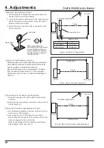
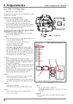
1000±10mm
900mm±2mm
A
AF chart
Fluorescent light stand
Camera
Center
Conversion lens
<Fig.B> Setup for AF Adjustment
Camera
Center
Gray chart
<Fig.C> Setup for Flash Adjustment
Lens holder
Stand
Base plate
When assembling the
conversion lens, take care to
ensure that the protruding
side is towards the subject,
and the flat side is towards
the camera lens.
(2)Setup for AF adjustment (Fig.B)
1. Set the distance between the conversion lens and
the tip of the lens to 900mm±2mm.
2. Use a light source to illuminate the AF chart. Ensure
that the luminance of the surface of the AF chart is
between 9.0Ev and 12.0Ev.
3. Ensure that the conversion lens is concentric with
the camera lens.
(3)Setup for Flash Adjustment (Fig.C)
Strobe adjustment is readily influenced by external light.
The periphery of the gray chart should therefore be as
dark as possible to minimize this influence.
Ensure that the gray chart is at a distance of 1000mm
from the camera reference face (*1). Use a Superior
Oxford Gray (No.22) chart, or a chart with reflectivity of
18±0.7%.
Conversion lens
Distance A
1560.69mm
25.16mm
865.12mm
30.64mm
932mm±2mm
Line chart
Fluorescent light stand
Camera
Center
<Fig.D> Setup for AF-Assist Light adjustment
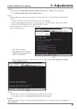
(4)Preparation for AF-Assist Light adjustment
1. Output the image to TV with a camera that works
normally.
2. Apply the sign according to the mark of the center of
the AF target [+].
(5)Setup for AF-Assist Light adjustment (Fig.D)
1. Set the distance between the Line Chart and the tip
of the lens to 932mm±2mm.
2. Use a light source to illuminate the Line chart.
Ensure that the luminance of the surface of the Line
chart is between 9.0Ev and 12.0Ev.
(Darken the lighting for the irradiation positioning
after suitable of the auto focus.)
Содержание FinePix S5000
Страница 20: ...20 3 Schematics FinePix S5000 Service Manual 3 6 CCD BLOCK Schematic Diagram ...
Страница 21: ...21 FinePix S5000 Service Manual 3 Schematics 3 7 CAMERA BLOCK Schematic Diagram ...
Страница 22: ...22 FinePix S5000 Service Manual 3 Schematics 3 8 PROCESS BLOCK Schematic Diagram ...
Страница 23: ...23 3 Schematics FinePix S5000 Service Manual 3 9 POWER BLOCK Schematic Diagram ...
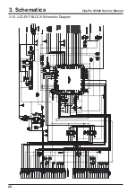
Страница 24: ...24 3 Schematics FinePix S5000 Service Manual 3 10 LCD EVF BLOCK Schematic Diagram ...
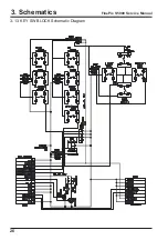
Страница 26: ...26 3 Schematics FinePix S5000 Service Manual 3 13 KEY SW BLOCK Schematic Diagram ...
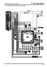
Страница 27: ...27 3 Schematics FinePix S5000 Service Manual 3 14 MOTOR BLOCK Schematic Diagram ...
Страница 28: ...28 3 Schematics FinePix S5000 Service Manual 3 15 POWER ON BLOCK Schematic Diagram ...
Страница 29: ...29 3 Schematics FinePix S5000 Service Manual 3 16 FLASH BLOCK Schematic Diagram ...
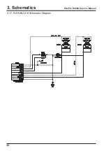
Страница 30: ...30 3 Schematics FinePix S5000 Service Manual 3 17 R SW BLOCK Schematic Diagram ...
Страница 32: ...32 3 Schematics FinePix S5000 Service Manual 3 20 MAIN PWB ASSY Component Locations Side A Side B ...
Страница 33: ...33 3 Schematics FinePix S5000 Service Manual 3 21 DCST PWB ASSY Component Locations Side A Side B ...
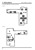
Страница 34: ...34 3 Schematics FinePix S5000 Service Manual 3 22 KSW PWB ASSY Component Locations Side A Side B ...
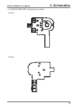
Страница 35: ...35 3 Schematics FinePix S5000 Service Manual 3 23 MSW PWB ASSY Component Locations Side A Side B ...
Страница 82: ...26 30 Nishiazabu 2 chome Minato ku Tokyo 106 8620 Japan FUJI PHOTO FILM CO LTD ...

