56
4. Adjustments
FinePix S5000 Service Manual
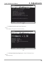
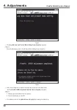
Fig.23
4-14. [F1] : Battery voltage adjustment
Caution:
1. When running battery adjustment, supply power (3V) to the camera using
the Battery jig
before setting the camera to
the Jig mode.
2. Always measure input voltage close to the battery connector.
3. When reducing voltage, ensure that it is not reduced excessively from the measured value, and adjust the regulated
power supply. Failure to do so may result in interruption of communication between the adjustment software and the
camera, and the adjustment software may produce an error. Restart the adjustment software in this case.
<Step 1>
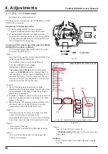
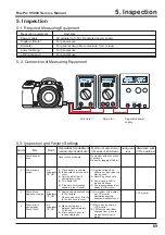
1. Connect as shown in the connection diagram.
Run the adjustment in accordance with the instructions on the screen.
2. Place the camera lens upwards (as the lens will operate, care is required).
When preparations are complete, select
[F1]
from the
[Adjustment Items Select Screen (Fig.5)]
.
(press the [F1] key on the keyboard)
---> The
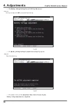
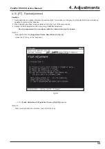
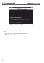
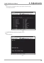
[Battery Voltage Preparation Screen (Fig.23)]
appears.
<Step 2>
When preparations are complete, press the Enter key.
USB CABLE
POWER CABLE JIG
Содержание FinePix S5000
Страница 20: ...20 3 Schematics FinePix S5000 Service Manual 3 6 CCD BLOCK Schematic Diagram ...
Страница 21: ...21 FinePix S5000 Service Manual 3 Schematics 3 7 CAMERA BLOCK Schematic Diagram ...
Страница 22: ...22 FinePix S5000 Service Manual 3 Schematics 3 8 PROCESS BLOCK Schematic Diagram ...
Страница 23: ...23 3 Schematics FinePix S5000 Service Manual 3 9 POWER BLOCK Schematic Diagram ...
Страница 24: ...24 3 Schematics FinePix S5000 Service Manual 3 10 LCD EVF BLOCK Schematic Diagram ...
Страница 26: ...26 3 Schematics FinePix S5000 Service Manual 3 13 KEY SW BLOCK Schematic Diagram ...
Страница 27: ...27 3 Schematics FinePix S5000 Service Manual 3 14 MOTOR BLOCK Schematic Diagram ...
Страница 28: ...28 3 Schematics FinePix S5000 Service Manual 3 15 POWER ON BLOCK Schematic Diagram ...
Страница 29: ...29 3 Schematics FinePix S5000 Service Manual 3 16 FLASH BLOCK Schematic Diagram ...
Страница 30: ...30 3 Schematics FinePix S5000 Service Manual 3 17 R SW BLOCK Schematic Diagram ...
Страница 32: ...32 3 Schematics FinePix S5000 Service Manual 3 20 MAIN PWB ASSY Component Locations Side A Side B ...
Страница 33: ...33 3 Schematics FinePix S5000 Service Manual 3 21 DCST PWB ASSY Component Locations Side A Side B ...
Страница 34: ...34 3 Schematics FinePix S5000 Service Manual 3 22 KSW PWB ASSY Component Locations Side A Side B ...
Страница 35: ...35 3 Schematics FinePix S5000 Service Manual 3 23 MSW PWB ASSY Component Locations Side A Side B ...
Страница 82: ...26 30 Nishiazabu 2 chome Minato ku Tokyo 106 8620 Japan FUJI PHOTO FILM CO LTD ...


