48
4. Adjustments
FinePix S5000 Service Manual
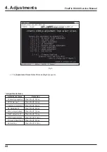
CCD Defect Data
ZJ00666-100
3021.zip
3022.zip
3043.zip
Data after decompression
30220279
30220286
30220280
30220287
30220288
30220278
30220310
4-11. [F4] : CCD data input
(CCD data input,OFD adjustment)
CCD data input is required when the LENS ASSY or MAIN
PWB ASSY is replaced.
[Obtaining CCD damage data]
1. When the LENS CONST has been replaced.
The data is supplied with the new LENS CONST.
2. When the MAIN PWB ASSY has been replaced.
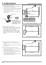
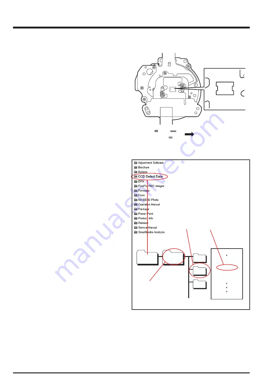
Note the CCD serial No. on the camera to be adjusted,
and copy the data with the same CCD Serial No. from
the CCD data file to a floppy disk.
Creating a CCD data floppy disk when the MAIN
PWB ASSY has been replaced.
* The following example assumes the use of the serial
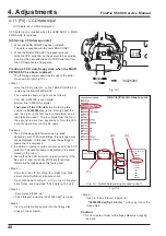
No. shown at right.(Fig.10-1)
<Step 1>
Note the CCD serial No. on the LENS CONST when
replacing the MAIN PWB ASSY.
The numbers shown at right are as follows.
First line: 0302200 (seven digits)
Bottom line: 0280C(five digits)
The name of the CCD data
file containing this
number is
30220280.dat
(ie the first digit and the
last two digits of the first line are discarded, and 2
to5 digits are used ). The four digits from the top in
the second line are then appended to form the CCD
data file name. Record this file name.
Cautions:
1. The CCD damage data file extension is
‘.dat’
.
Depending upon Windows settings, this extension may
not be displayed. In this case, change the settings to
ensure that it is displayed.
2. In addition to numbers, letters are also used in the CCD
serial No. The data file name is instructed in the same
manner in this case.
3. Ensure that the CCD serial No. is read correctly. If the
file name is read incorrectly CCD data for another
camera will be loaded when this file is used.
<Step 2>
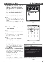
Download the ZIP file of top four digits from Web
server (http://fujifilm-di.intranets.com/).
Open [ZJ00666-100(Fig.10-2-(1)] in the CCD defect
data folder, and download "3022.zip[Fig.10-2-(2)]".
<Step 3>
Decompress "3022.zip".
-->"3022 folders" including "30220280.dat" is made.
<Step 4>
Insert a writable floppy disk into the floppy disk
drive on the computer.
(2)
(3)
(1)
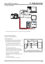
< Fig. Q> Defect data making procedure chart
(http://fujifilm-di.intranets.com/).
Fig.10-2
<Step 5>
Open in "3022 folders", search for
"30220280.dat[Fig.10-2-(3)] "
, and copy it onto the
floppy disk.
Caution:
1. Do not create a folder on the floppy disk when copying
the data.
Fig.10-1
0280C
0302200
0280C
0302200
0302200
0280C
30220280
Содержание FinePix S5000
Страница 20: ...20 3 Schematics FinePix S5000 Service Manual 3 6 CCD BLOCK Schematic Diagram ...
Страница 21: ...21 FinePix S5000 Service Manual 3 Schematics 3 7 CAMERA BLOCK Schematic Diagram ...
Страница 22: ...22 FinePix S5000 Service Manual 3 Schematics 3 8 PROCESS BLOCK Schematic Diagram ...
Страница 23: ...23 3 Schematics FinePix S5000 Service Manual 3 9 POWER BLOCK Schematic Diagram ...
Страница 24: ...24 3 Schematics FinePix S5000 Service Manual 3 10 LCD EVF BLOCK Schematic Diagram ...
Страница 26: ...26 3 Schematics FinePix S5000 Service Manual 3 13 KEY SW BLOCK Schematic Diagram ...
Страница 27: ...27 3 Schematics FinePix S5000 Service Manual 3 14 MOTOR BLOCK Schematic Diagram ...
Страница 28: ...28 3 Schematics FinePix S5000 Service Manual 3 15 POWER ON BLOCK Schematic Diagram ...
Страница 29: ...29 3 Schematics FinePix S5000 Service Manual 3 16 FLASH BLOCK Schematic Diagram ...
Страница 30: ...30 3 Schematics FinePix S5000 Service Manual 3 17 R SW BLOCK Schematic Diagram ...
Страница 32: ...32 3 Schematics FinePix S5000 Service Manual 3 20 MAIN PWB ASSY Component Locations Side A Side B ...
Страница 33: ...33 3 Schematics FinePix S5000 Service Manual 3 21 DCST PWB ASSY Component Locations Side A Side B ...
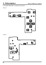
Страница 34: ...34 3 Schematics FinePix S5000 Service Manual 3 22 KSW PWB ASSY Component Locations Side A Side B ...
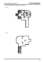
Страница 35: ...35 3 Schematics FinePix S5000 Service Manual 3 23 MSW PWB ASSY Component Locations Side A Side B ...
Страница 82: ...26 30 Nishiazabu 2 chome Minato ku Tokyo 106 8620 Japan FUJI PHOTO FILM CO LTD ...

