2
FinePix S5000 Service Manual
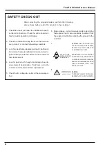
6. Make leakage - current measurements to determine
that exposed parts are acceptably insulated from
the supply circuit before returning the product to the
customer.
7.
CAUTION:
FOR CONTINUED PRO-
TECTION AGAINST FIRE HAZARD,
REPLACE ONLY WITH SAME TYPE
2.5 AMPERES 125V FUSE.
ATTENTION:
AFIN D'ASSURER
UNEPROTECTION PERMANENTE
CONTRE LES RISQUES D'INCENDIE,
REMPLACER UNIQUEMENT PAR UN
FUSIBLE DE MEME, TYPE 2.5 AM-
PERES, 125 VOLTS.
8.
WARNING:
TO REDUCE THE ELECTRIC SHOCK,
BE CAREFUL TO TOUCH THE PARTS.
WARNING!
HIGH VOLTAGE
SAFETY CHECK-OUT
After correcting the original problem, perform the following
safety check before return the product to the costomer.
1. Check the area of your repair for unsoldered or poorly
sol dered connections. Check the entire board sur-
face for solder splasher and bridges.
2. Check the interboard wiring to ensure that no wires
are “pinched” or contact high-wattage resistors.
3. Look for unauthorized replacement parts, particuarly
tran sistors, that were installed during a previous re-
pair. Point them out to the customer and recommend
their replacement.
4. Look for parts which, though functioning, show ob-
vious signs of deterioration. Point them out to the
customer and recommend their replacement.
5. Check the B + voltage to see it is at the values speci-
fied.
2.5A 125V
2.5A 125V
RISK OF FIRE-
REPLACE FUSE
AS MARKED
Содержание FinePix S5000
Страница 20: ...20 3 Schematics FinePix S5000 Service Manual 3 6 CCD BLOCK Schematic Diagram ...
Страница 21: ...21 FinePix S5000 Service Manual 3 Schematics 3 7 CAMERA BLOCK Schematic Diagram ...
Страница 22: ...22 FinePix S5000 Service Manual 3 Schematics 3 8 PROCESS BLOCK Schematic Diagram ...
Страница 23: ...23 3 Schematics FinePix S5000 Service Manual 3 9 POWER BLOCK Schematic Diagram ...
Страница 24: ...24 3 Schematics FinePix S5000 Service Manual 3 10 LCD EVF BLOCK Schematic Diagram ...
Страница 26: ...26 3 Schematics FinePix S5000 Service Manual 3 13 KEY SW BLOCK Schematic Diagram ...
Страница 27: ...27 3 Schematics FinePix S5000 Service Manual 3 14 MOTOR BLOCK Schematic Diagram ...
Страница 28: ...28 3 Schematics FinePix S5000 Service Manual 3 15 POWER ON BLOCK Schematic Diagram ...
Страница 29: ...29 3 Schematics FinePix S5000 Service Manual 3 16 FLASH BLOCK Schematic Diagram ...
Страница 30: ...30 3 Schematics FinePix S5000 Service Manual 3 17 R SW BLOCK Schematic Diagram ...
Страница 32: ...32 3 Schematics FinePix S5000 Service Manual 3 20 MAIN PWB ASSY Component Locations Side A Side B ...
Страница 33: ...33 3 Schematics FinePix S5000 Service Manual 3 21 DCST PWB ASSY Component Locations Side A Side B ...
Страница 34: ...34 3 Schematics FinePix S5000 Service Manual 3 22 KSW PWB ASSY Component Locations Side A Side B ...
Страница 35: ...35 3 Schematics FinePix S5000 Service Manual 3 23 MSW PWB ASSY Component Locations Side A Side B ...
Страница 82: ...26 30 Nishiazabu 2 chome Minato ku Tokyo 106 8620 Japan FUJI PHOTO FILM CO LTD ...


