39
4. Adjustments
FinePix S5000 Service Manual
the adjustment software.
* The adjustment software will not operate correctly
unless the FinePixF_S5000_W folder is located in the
C:\ directory. Do not change the directory configura-
tion or folder name.
4-8. Initializing the Adjustment Software
* As the initial setup is located in the [FFW.ini] file,
follow the procedure below. Note that the software will
not run if the file name is changed.
* As the initialization described in Steps 3, 4, 5, and 6 is
included in the [FFW.ini] file, the user is only required
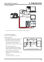
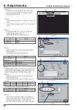
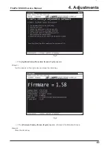
<Fig.E>
<Fig.F>
to check details.
* Do not overwrite the user program (FX_S5000_W.ff)
under any circumstances. The software will not run if
the user program is overwritten.
4-7. Installing and Starting the Adjust-
ment Software
<Step 1>
Insert the FinePix_ S5000_W adjustment software
media (ZJ00674-100) in the drive on the PC.
<Step 2>
Copy each of the folders in the [FinePix_S5000_W]
folder to the C: drive on the PC (Fig.E).
<Step 3>
When all the folders have been copied to the C:
drive, double-click on
[C:\FinePix_S5000_W\FFW.exe] (Fig.E) to start
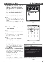
<Fig.D>
4-6. Installing the Jig Drivers on the PC
* As this device uses a USB interface for communica-
tions with the PC, the [USB Jig Driver] must first be
installed on the PC before the PC adjustment software
can be run.
* As the USB Jig Driver is the same for all models after
March 2003, this jig driver is already installed on the
PC. This driver software need not be installed on PCs
in which the USB device is already been adjusted.
<Step 1>
Insert the DSC jig driver setup floppy disk (ZJ00476-
101) in the floppy disk drive on the PC.
<Step 2>
Double-click on [setup.exe](Fig.D) on the floppy disk,
and follow the instructions on the screen to install the
jig driver.
The jig driver will be saved in [C:\Program Files\Fig].
Содержание FinePix S5000
Страница 20: ...20 3 Schematics FinePix S5000 Service Manual 3 6 CCD BLOCK Schematic Diagram ...
Страница 21: ...21 FinePix S5000 Service Manual 3 Schematics 3 7 CAMERA BLOCK Schematic Diagram ...
Страница 22: ...22 FinePix S5000 Service Manual 3 Schematics 3 8 PROCESS BLOCK Schematic Diagram ...
Страница 23: ...23 3 Schematics FinePix S5000 Service Manual 3 9 POWER BLOCK Schematic Diagram ...
Страница 24: ...24 3 Schematics FinePix S5000 Service Manual 3 10 LCD EVF BLOCK Schematic Diagram ...
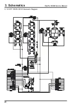
Страница 26: ...26 3 Schematics FinePix S5000 Service Manual 3 13 KEY SW BLOCK Schematic Diagram ...
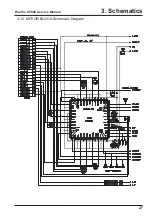
Страница 27: ...27 3 Schematics FinePix S5000 Service Manual 3 14 MOTOR BLOCK Schematic Diagram ...
Страница 28: ...28 3 Schematics FinePix S5000 Service Manual 3 15 POWER ON BLOCK Schematic Diagram ...
Страница 29: ...29 3 Schematics FinePix S5000 Service Manual 3 16 FLASH BLOCK Schematic Diagram ...
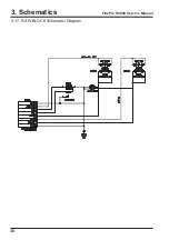
Страница 30: ...30 3 Schematics FinePix S5000 Service Manual 3 17 R SW BLOCK Schematic Diagram ...
Страница 32: ...32 3 Schematics FinePix S5000 Service Manual 3 20 MAIN PWB ASSY Component Locations Side A Side B ...
Страница 33: ...33 3 Schematics FinePix S5000 Service Manual 3 21 DCST PWB ASSY Component Locations Side A Side B ...
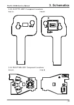
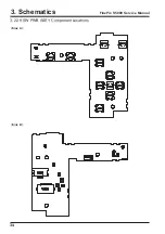
Страница 34: ...34 3 Schematics FinePix S5000 Service Manual 3 22 KSW PWB ASSY Component Locations Side A Side B ...
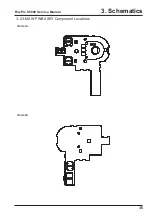
Страница 35: ...35 3 Schematics FinePix S5000 Service Manual 3 23 MSW PWB ASSY Component Locations Side A Side B ...
Страница 82: ...26 30 Nishiazabu 2 chome Minato ku Tokyo 106 8620 Japan FUJI PHOTO FILM CO LTD ...

