3
TABLE OF CONTENTS
FinePix S3Pro Service Manual
TABLE CONTENTS
1. General ........................................................... 4
1-1. Product specification .............................................. 4
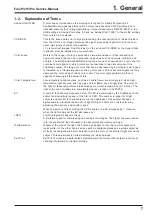
1-2. Explanation of Terms .............................................. 7
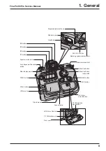
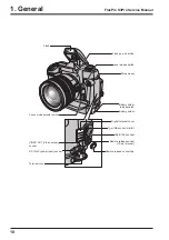
1-3. Names of External Components ............................ 8
2. Disassembly ................................................. 11
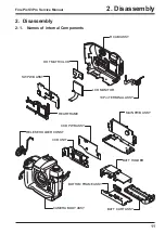
2-1. Names of internal Components ............................ 11
2-2. Removing the BATT CART ASSY ........................ 12
2-3. Removing the R CABI ASSY ................................ 12
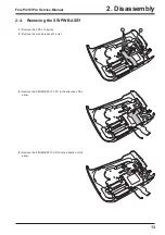
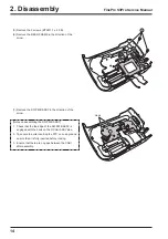
2-4. Removing the SW PWB ASSY ............................. 13
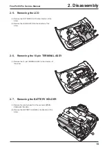
2-5. Removing the LCD ............................................... 15
2-6. Removing the 10-pin TERMINAL ASSY ............... 15
2-7. Removing the BATTERY HOLDER ...................... 15
2-8. Removing the MAIN PWB ASSY .......................... 16
2-9. Removing the CCD PWB ASSY and CCD UNIT ...... 17
2-10. How to dismantle the parts around the outer
wrappings ............................................................. 19
2-10-1. Removing TOP COVER UNIT ................ 19
2-10-2. Removing SB LOWER CASE UNIT ....... 21
3. Schematic ..................................................... 23
Overview of the new technology ............. 23
Block function descriptions ..................... 24
Description of the Power Supply Block
Functions ................................................ 24
3-4. Block Diagram ...................................................... 25
3-5. Overall connection Diagram ................................. 26
3-6. Circuit Diagrams ................................................... 27
CCD BLOCK ........................................... 27
DCDC BLOCK ........................................ 28
IEEE1394 BLOCK .................................. 29
PROCESS BLOCK ................................. 30
CARD BLOCK ........................................ 31
DCDC BLOCK (CAMERA BODY) .......... 31
PARTNER-CHIP BLOCK ........................ 32
PWON BLOCK ....................................... 33
USB2.0 BLOCK ...................................... 34
3-6-10. LCD BLOCK ........................................... 35
3-6-11. SW BLOCK ............................................. 36
3-7. Mounted Parts Diagrams ...................................... 37
CCD PWB ASSY .................................... 37
MAIN PWB ASSY ................................... 38
SW PWB ASSY ...................................... 40
4. Adjustments .................................................. 41
4-1. Important point Adjustment when
Replacing Major Parts .......................................... 41
4-2. Measuring Instruments Used ............................... 41
4-3. Use Jig list ............................................................ 41
4-4. Calibration method of pattern box ........................ 43
4-5. Adjusting soft installation ...................................... 43
Installation of DSC jig driver ................... 44
Adjusting soft initiation method ............... 44
4-6. Initial Settings of the Adjustment Software ........... 45
4-7. Starting the Adjustment Software ......................... 48
4-8. [F4] : CCD Defect Correction ............................... 51
4-9. [F5] : CAMERA Adjustment .................................. 53
4-10. [F1] : Battery Voltage Adjustment ......................... 56
4-11. [F11] : Video Adjustment ...................................... 60
4-12. [F2] : Rear LCD Panel Adjustment ....................... 62
4-13. [F8] : Firmware Download .................................... 64
4-14. [F12] : End Setting ................................................ 66
5. Inspection ..................................................... 71
5-1. Measuring Instruments and Jigs Used for
Inspection ............................................................. 71
5-2. Connection of Measuring Instruments for
Inspection ............................................................. 71
5-3. Inspection and Settings at Shipment .................... 72
5-4. Resolution Checking ............................................ 76
5-5. CCD Cleaning and Inspection Procedures ........... 78
CCD Cleaning Using a
Visual Inspection for Dusting .................. 78
CCD Cleaning Using
Test Photography to Detect Dusting ....... 79
5-6. AF Checking ......................................................... 80
Measuring equipment and tools
used for AF checking .............................. 80
Settings for the measuring equipment
and tools used for AF checking .................. 80
AF testing procedure .............................. 81
Cause identification procedure for
focus-related problems ........................... 82
6. Parts List ....................................................... 83
6-1. Packing and Accessories ..................................... 83
US-model ................................................ 83
CA-model ................................................ 84
EU-model ................................................ 85
EG-model ................................................ 86
GE-model ................................................ 87
AS-model ................................................ 88
JP-model ................................................. 89
6-2. Transportable form and necessary parts for
camera body repair .............................................. 90
6-3. CAMERA BODY ................................................... 91
6-4. R CABI ................................................................. 92
6-5. Internal parts ........................................................ 93
US/CA-model .......................................... 93
EU/EG/GE/AS-model .............................. 94
JP-model ................................................. 95
6-6. List of parts related to exterior .............................. 96
TOP COVER 1 ........................................ 96
TOP COVER 2 ........................................ 97
TOP COVER 3 ........................................ 98
CAMERA BODY External ....................... 99
. Electrical parts .................................................... 100
7. Appendix..................................................... 101
7-1. List of Related Technical Updates Issued .......... 101
Содержание FinePix S3Pro
Страница 27: ...27 3 Schematics FinePix S3Pro Service Manual 3 6 Circuit Diagrams 3 6 1 CCD BLOCK ...
Страница 28: ...28 3 Schematics FinePix S3Pro Service Manual 3 6 2 DCDC BLOCK ...
Страница 29: ...29 3 Schematics FinePix S3Pro Service Manual 3 6 3 IEEE1394 BLOCK ...
Страница 30: ...30 3 Schematics FinePix S3Pro Service Manual 3 6 4 PROCESS BLOCK ...
Страница 31: ...31 3 Schematics FinePix S3Pro Service Manual 3 6 5 CARD BLOCK 3 6 6 DCDC BLOCK CAMERA BODY ...
Страница 32: ...32 3 Schematics FinePix S3Pro Service Manual 3 6 7 PARTNER CHIP BLOCK ...
Страница 33: ...33 3 Schematics FinePix S3Pro Service Manual 3 6 8 PWON BLOCK ...
Страница 34: ...34 3 Schematics FinePix S3Pro Service Manual 3 6 9 USB2 0 BLOCK ...
Страница 35: ...35 3 Schematics FinePix S3Pro Service Manual 3 6 10 LCD BLOCK ...
Страница 36: ...36 3 Schematics FinePix S3Pro Service Manual 3 6 11 SW BLOCK ...
Страница 37: ...37 3 Schematics FinePix S3Pro Service Manual 3 7 Mounted Parts Diagrams 3 7 1 CCD PWB ASSY SIDE A SIDE B ...
Страница 38: ...38 3 Schematics FinePix S3Pro Service Manual 3 7 2 MAIN PWB ASSY SIDE A ...
Страница 39: ...39 3 Schematics FinePix S3Pro Service Manual SIDE B ...
Страница 40: ...40 3 Schematics FinePix S3Pro Service Manual 3 7 3 SW PWB ASSY SIDE A SIDE B ...
Страница 102: ...26 30 Nishiazabu 2 chome Minato ku Tokyo 106 8620 Japan FUJI PHOTO FILM CO LTD ...


