


8-11
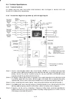
(Note 6) For the wiring of the control circuit, use shielded or twisted wires. When using shielded wires,
connect the shields to earth. To prevent malfunction due to noise, keep the control circuit wiring
away from the main circuit wiring as far as possible (recommended: 10 cm or longer), and never
set them in the same wire duct. When crossing the control circuit wiring with the main circuit
wiring, set them at right angles.
(Note 7) It is recommended for noise control that 3-phase, 4-wire cable be used for the motor wiring.
Connect grounding wires of the motor to the grounding terminal
z
G on the inverter.
The basic connection diagram above is for running/stopping the inverter and setting the frequency
with external signals. Given below are connection notes.
(1) Set function code F02 to "1" (External signals).
(2) Set function code F01 to "1" (Voltage input to terminal [12]) or "2" (Current input to terminal
[C1]).
(3) Short-circuit terminals [FWD] and [CM] to run the motor in the forward direction and opening
them to stop it. Short-circuit terminals [REV] and [CM] to run the motor in the reverse direction
and opening them to stop it.
(4) Frequency by voltage input is within the range from 0 to +10 VDC or 0 to the maximum
frequency. Frequency by current input is within the range from +4 to +20 mADC or 0 to the
maximum frequency.


