


5-22
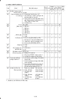
Data for
F01, C30
Function
2
Enable the current input to terminal [C1] (+4 to +20 mA DC or 0 to +20 mA DC,
maximum frequency obtained at +20 mA DC).
Using function code C40 expands the input range from "+4 to +20 mA DC"
to "0 to +20 mA DC."
3
Enable the sum of voltage (0 to +10 VDC, maximum frequency obtained at +10
VDC) and current inputs (+4 to +20 mA DC or 0 to +20 mA DC, maximum
frequency obtained at +20 mA DC) given to terminals [12] and [C1], respectively.
Using function code C40 expands the input range from "+4 to +20 mA DC"
to "0 to +20 mA DC."
Note: If the sum exceeds the maximum frequency (F03, A01), the maximum
frequency will apply.
4
Enable the built-in potentiometer (POT). (Maximum frequency obtained at full
scale of the POT)
7
Enable
UP
and
DOWN
commands assigned to the digital input terminals.
The
UP
and
DOWN
should be assigned to any of digital input terminals [X1] to
[X3] beforehand with any of E01 to E03 (data = 17 and 18).
In addition to the frequency command sources described above, higher priority
command sources including communications link and multistep frequency are
provided. For details, refer to the block diagram given in FRENIC-Mini User's
Manual (24A7-E-0023), Chapter 4, Section 4.2 "Drive Frequency Command
Generator."
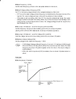
• For frequency settings made by terminals [12] (voltage) and [C1] (current) and by
the built-in potentiometer, setting the gain and bias changes the relationship
between those frequency settings and the drive frequency. Refer to function
code F18 for details.
• For the inputs to terminals [12] (voltage) and [C1] (current), low-pass filters can
be enabled.
• Using the terminal command
Hz2/Hz1
assigned to one of the digital input
terminals switches between frequency command 1 (F01) and frequency
command 2 (C30). Refer to function codes E01 to E03.
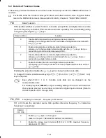
F02
Operation Method
F02 selects the source that specifies a run command for running the motor.
Data for F02
Run Command Source
Description
0
Keypad
(Rotation direction
specified by terminal
command)
Enable the
/
keys to run and stop the motor.
The rotation direction of the motor is specified by
terminal command
FWD
or
REV
.
1
External signals
Enable terminal command
FWD
or
REV
to run and
stop the motor.
2
Keypad
(Forward rotation)
Enable
/
keys to run and stop the motor. Note
that this run command enables only the forward
rotation.
There is no need to specify the rotation direction.


